

According to the Von Neumann architecture, a modern computer consists of three main parts which are input device or input unit, CPU or Central Processing Unit, and output device or output unit. Now in the tutorial on microprocessors, we stated that the microprocessor acts as a CPU but the microcontroller can act as a computer itself.
Microcontrollers are electronic components, made with fundamental components like resistors, capacitors, inductor, transistors fabricated on a small semiconductor chip which can be programmed to perform multi-disciplinary tasks. Microcontrollers have RAM, ROM, serial ports, I/O pins, and CPU integrated into the same chip. This is why microcontrollers are very easy to use. In this tutorial, we are going to discuss one of the most popular microcontrollers- ATmega328P.
Specifications of ATmega328P:
ATmega328P is a high-performance microcontroller made by ATMEL company. The specifications of this microcontroller are:
- It is available in PDIP, TQFP, QNF, MLF packages.
- It is an 8-bit AVR or Advanced Virtual RISC microcontroller.
- It’s PDIP and MLF packages have 28 pins, among which 23 pins are programmable input-output pins. There are 6 PWM pins, 6 analog pins, and a total of 14 digital pins in this microcontroller. In the case of TQFP and QNF packages, there are 32 pins and a total of 8 analog pins.
- Flash Memory of 32KB, 2KB of SRAM or Static Random-Access memory, and 1KB of EEPROM or Electrically Erasable Programmable Read-Only Memory.
- ATmega has 3 timers, one of them is 16bit and the other two are of 8 bits.
- It supports I2C, SPI serial interface.
- It can be programmed by serial USART
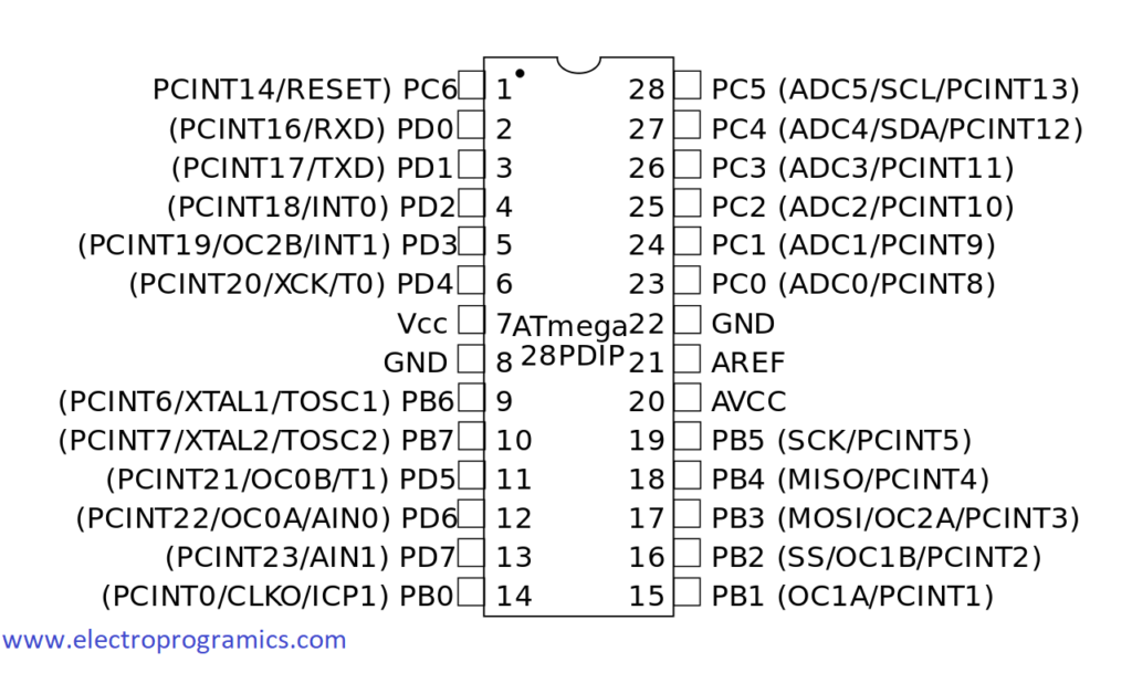
Pin Diagram of ATmega328P
The pin details, given here are for the PDIP package:
| PinNo. | PinName | PinFunction | Description |
| 1 | PC6 | Reset | When this pin is connected to ground, it resets the program of the microcontroller. |
| 2 | PD0 | Digital Pin (RX) | It acts as data receiver pin. |
| 3 | PD1 | Digital Pin (TX) | It acts as data transmitter pin. |
| 4 | PD2 | Digital Pin | It acts as digital I/O pin |
| 5 | PD3 | Digital Pin (PWM) | It acts as digital I/O pin and can be used for PWM purpose |
| 6 | PD4 | Digital Pin | It acts as digital I/O pin |
| 7 | VCC | Positive Voltage | This pin is connected to the positive terminal of the power supply |
| 8 | GND | Ground | This pin is connected to ground. |
| 9 | XTAL1 | Crystal Oscillator | This pin is connected to an external oscillator to provide a higher clock pulse. |
| 10 | XTAL2 | Crystal Oscillator | This pin is connected to an external oscillator to provide a higher clock pulse. |
| 11 | PD5 | Digital Pin (PWM) | It acts as digital I/O pin and can be used for PWM purpose |
| 12 | PD6 | Digital Pin (PWM) | It acts as digital I/O pin and can be used for PWM purpose |
| 13 | PD7 | Digital Pin | It acts as digital I/O pin |
| 14 | PB0 | Digital Pin | It acts as digital I/O pin |
| 15 | PB1 | Digital Pin (PWM) | It acts as digital I/O pin and can be used for PWM purpose |
| 16 | PB2 | Digital Pin (PWM) | It acts as digital I/O pin and can be used for PWM purpose |
| 17 | PB3 | Digital Pin (PWM & MOSI) | It acts as digital I/O pin, can be used for PWM purpose and is used for SPI communication. |
| 18 | PB4 | Digital Pin (MISO) | It acts as digital I/O pin and is used for SPI communication. |
| 19 | PB5 | Digital Pin | It acts as digital I/O pin |
| 20 | AVCC | Positive Voltage | This voltage is used to power up ADC |
| 21 | AREF | Reference | This is a reference voltage for ADC |
| 22 | GND | Ground | This pin is connected to ground. |
| 23 | PC0 | Analog Pin | Analog to digital channel 0 |
| 24 | PC1 | Analog Pin | Analog to digital channel 1 |
| 25 | PC2 | Analog Pin | Analog to digital channel 2 |
| 26 | PC3 | Analog Pin | Analog to digital channel 3 |
| 27 | PC4 | Analog Pin | Analog to digital channel 4 |
| 28 | PC5 | Analog Pin | Analog to digital channel 5 |
To summarize this, we have given a pin diagram below:
Advantages of ATmega328P
ATmega328P provides us some great advantages that make it one best choice for both engineers and hobbyists. Some of its advantages are:
- Its power consumption is very low. At the active mode, it consumes 1.5mA at 3V, and a power-down mode, it consumes 1 Micro Ampere at 3V.
- It has an advanced RISC (or Reduced Instruction Set Computing) structure.
- It has an internal ADC or Analog to Digital Converter.
- Overall 6 PWM pins, 6 to 8 analog pins, and a total of 14 digital I/O pins.
- It can be operated between 1.8 to 5.5 volts which is a standard voltage range.
- It has a temperature range of -40 to +125 degrees centigrade which makes it easier to solder.
- ATmega programmed using Arduino IDE
- There are many open-source codes available for this microcontroller on the internet.
- It has one TX and one RX pin using which it can be attached with wired or wireless communication modules and devices.
Applications of ATmega328P
It has already been stated before that ATmega328P is one of the most widely used microcontrollers. Some of its major applications are:
- Arduino: ATmega328P is being used by the Arduino company. It is being used in major boards of Arduino whether it is Arduino UNO, Nano, or Mini, etc.
- Security systems: One of the most popular usages of ATmega328P due to the availability of a large number of opensource hardware and software.
- Robots & Drones: To make robots like line followers, land-rovers, and drones like a quadcopter, many engineers and hobbyists prefer this microcontroller.
- Wireless communication: As this microcontroller has TX and RX pins, it can be used for wireless communication purposes.
- IoT: Nowadays, ATmega328P is being used in the field of IoT.
- Home Automation: ATmega328P is widely used for home automation purposes.
These are just a few examples. There are many many more applications of this microcontroller.
Finally, this is all about a detailed overview of ATmega328P. You can even download the datasheet here. If there are any queries on this topic feel free to ask in the comment box. We are always here to help you out. Will be back with the next article soon.
