
How to blink an led with Raspberry pi 3B+
Introduction
In this tutorial, you will learn how to connect the LED with the Raspberry pi, a microprocessor board commonly known as a single board computer and write the code to the board and control the accordingly.
About Raspberry pi 3B+
Raspberry pi is an ARM architecture based single board computer having 1GB RAM with a faster 1.4GHZ processor and it’s mainly used for IOT(internet of things).
Components Required
- Raspberry pi 3B+ – Buy Now
- LED – Buy Now
- Resistor – 1kΩ – Buy Now
- Bread Board – Buy Now
- Jumper Wires – Buy Now
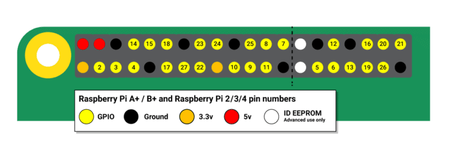
Pinout of Raspberry pi 3B+ :

Circuit diagram
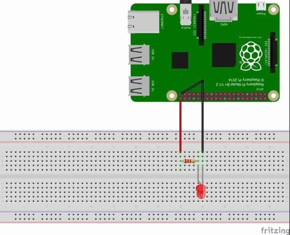
First of all connect the positive pin of led to pin number 40(GPIO 21) and negative pin to pin number 39 (ground) of the Raspberry pi.
Its not compulsion to add resistance as Raspberry pi only provide 15 amps to the led which is not dangerous at all but for safety please add a 1kΩ resistance between pin number 40 and positive of led pin
Working explanation of blinking LED with Raspberry Pi microprocessor:
- First of all setup the Raspberry pi and click on the top left corner menu on the desktop and then go to programming and choose python

- After that click on new file in the file menu of python ide

- Next write the code given below in python idle.
import RPi.GPIO as IO            # calling header file for GPIO’s of PI
import time                              # calling for time to provide delays in program
IO.setmode (IO.BOARD)       # programming the GPIO by BOARD pin numbers, GPIO21 is called as PIN40
IO.setup(40,IO.OUT)             # initialize digital pin40 as an output.
IO.output(40,1)                      # turn the LED on (making the voltage level HIGH)
time.sleep(1)                         # sleep for a second
IO.cleanup()                         # turn the LED off (making all the output pins LOW)
time.sleep(1)                        #sleep for a second
#loop is executed second time
IO.setmode (IO.BOARD)
IO.setup(40,IO.OUT)
IO.output(40,1)
time.sleep(1)
IO.cleanup()
time.sleep(1)
#loop is executed third time
IO.setmode (IO.BOARD)
IO.setup(40,IO.OUT)
IO.output(40,1)
time.sleep(1)
IO.cleanup()
time.sleep(1)- Now save the code as blink.py on desktop

- Go to run and run module

- Now you see that led start blinking.
CONCLUSION
In this manner you can upload the code into the microprocessor board accordingly and can control the LED, depending on your requirement. You can also modify the code as for your convenience. This completes the tutorial and for any queries comment box is always open for you.
AUTHOR CREDIT:
