
Interfacing 7-Segment Display with PIC Microcontroller
Introduction
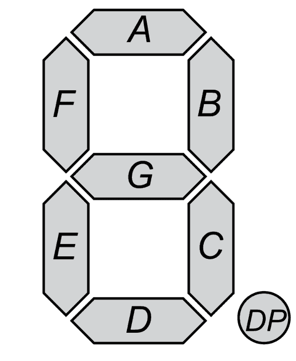
A seven-segment display can be used to generate a number from 0 to 9, it consists of 7 bar-like LEDs arranged in the shape of the number 8, and another dot-shaped LED at the bottom right. These LEDs are identified clockwise from the top as letters from a to g. This tutorial deals with the interfacing 7-Segment display with a PIC microcontroller.
These displays have 9 pins, the first 8 for the LEDs and the 9th pin is the common pin.
There are two types of 7-segment displays:
1. Common cathode display: The cathodes of the LEDs are connected to the ground. To do this we connect the common pin to the ground and the LED pins to the microcontroller.
2. Common anode display: The anodes of the LEDs are connected to the ground. To accomplish this, the common pin is given a positive voltage and the LED pins are connected to the ground.
In our project, we will be using the common cathode-type configuration. The truth table for displaying each number is shown below.

The arrangement of the binary values for each of the numbers can be written in hexadecimal format and fed to the microcontroller.
Aim:
To interface 7 segment display with PIC16F877A
Procedure:
1. Open MPLAB and make a new project.
2. Make a new “main.c” file.
3. Write down the code for 7 segment display.
4. Click on the build.
5. Now go to Proteus and set up the components as seen in the video.
6. Double click on the microcontroller and set the processor clock frequency as 20 mHz and open the. hex file of the program you just wrote in the program file field.
7. On the bottom left corner, click on run.
Code:
/*
 * File:   main.c
 * Author: Nabanil Mitra
 *
 */


#include <xc.h>
#define _XTAL_FREQ 20000000
// CONFIG
#pragma config FOSC = HS        // Oscillator Selection bits (HS oscillator)
#pragma config WDTE = OFF       // Watchdog Timer Enable bit (WDT disabled)
#pragma config PWRTE = OFF      // Power-up Timer Enable bit (PWRT disabled)
#pragma config BOREN = OFF      // Brown-out Reset Enable bit (BOR disabled)
#pragma config LVP = ON         // Low-Voltage (Single-Supply) In-Circuit Serial Programming Enable bit (RB3/PGM pin has PGM function; low-voltage programming enabled)
#pragma config CPD = OFF        // Data EEPROM Memory Code Protection bit (Data EEPROM code protection off)
#pragma config WRT = OFF        // Flash Program Memory Write Enable bits (Write protection off; all program memory may be written to by EECON control)
#pragma config CP = OFF         // Flash Program Memory Code Protection bit (Code protection off)

unsigned char segment[]={0x3f,0x06,0x5b,0x4f,0x66,0x6d,0x7d,0x07,0x7f,0x6f},i=0;
void main(void)
{
    TRISC = 0x00;
    while(1)
    {

        for(i=0;i<10;i++)
        {
           PORTC = segment[i];
           __delay_ms(1000);
        }

    }
    return;
}