Home automation using bluetooth and Arduino

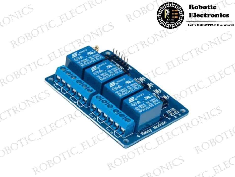
Home automation using bluetooth and Arduino In this article, I am going to tell you how to make the Home automation using bluetooth and Arduino. You can control your home appliances using your smartphone easily. These can be used in houses, apartments, hotels, etc.  I want to know how to make this project and make your home automated. Step 1: Components Required Hardware :     Arduino UNO     2 channel Relay     230V AC supply     Jumper Wires     HC05 Bluetooth Module Arduino UNO Relay bluetooth module Software :     Arduino IDE     Blynk App Step 2: Blynk Setup First of all, download the Blynk app on an Android device. Register with your device. Click on ‘create a new project Select your project name (eg: Home automation) Choose your board: Arduino UNO Choose connection type: Bluetooth And click on the create button. Hence, your project is ready to edit. An email will be sent to your mail-id. Copy the authentication code from your mail. Now, install the blynk libraries to your Arduino IDE. You have to paste the Auth token in the Arduino code. Now, your Arduino is ready to take instructions from the app. Let’s create the functions to be performed in the Blynk app. Step 3: Blynk Interface Click on add widget button to create your operations. Select the ‘Bluetooth’ widget and the 2 buttons to control 2 devices in your home. If you want to control more number of devices you can add buttons to your requirement. Now, customize the button settings to acts as a switch. Select the digital pin in the Arduino that you are using to control specific appliances. After making the necessary connections, customize Bluetooth settings to connect to your HCO5 device.Step 4: Connections The connections are very simple. There are 6 pins for HCO5 from which we use only 4 pins (TX, RX, VCC, GND). The TX and RX pins are connected to 10,11 pins respectively. VCC is connected to 3.3v pin on Arduino. GND pin is connected to the GND pin of Arduino.   Note1: Take care that the pins TX and RX of the Bluetooth are not connected to Arduino during the uploading of the code. After the code is uploaded, we can connect them to their respective pins.   Relay is simply an Electronic switch used to control electrical appliances. A 2- channel relay has 4 pins to be connected to Arduino (VCC, GND, D0, D1). The VCC and GND are connected to the respective pins of Arduino. With the pins D0, D1 we can control 2 appliances of our home. Let these pins to be connected to D2, D3 pins of Arduino since we used the same pins for buttons in BLYNK app.  The other side of the relay has 3 connections namely NC (Normally Connected), COM ( common), and NO (Normally Open). Connect the positive terminal of the lamp to the positive terminal of the AC supply. Now break the negative terminal of the lamp and connect one end to COM pin and another end to NO pin of the relay. Now, The circuit is ready to be executed. Step 5: Code The Arduino code requires some standard libraries to perform this project namely “blynk” And “SoftwareSerial.h”   The Arduino code is as follows : Note2: Check whether the libraries are successfully installed in your software.After completion of coding and using the Auth Token in the code, we have to setup Arduino IDE.go to  TOOLS / BOARD /GENUINE UNO andTOOLS/ PORT/COM_Now your software setup is complete. Upload your code (refer Note 1) and you are ready to test your project.  Conclusion :  Hence, the prerequisite required to make the project Home Automation using Bluetooth is ready to be followed. As it doesn’t require the Internet, It can be used anywhere in the world.

DRONE PROPELLERS

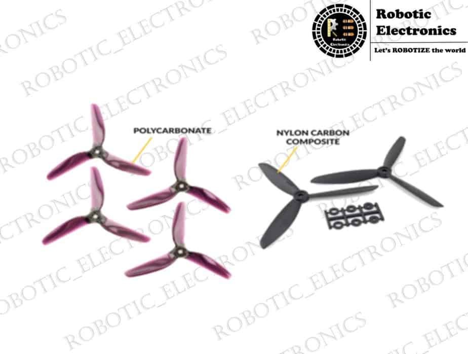
DRONE PROPELLERS We have discussed the evolution of drones and different types of drones in the previous session. Have you ever wondered how a drone flies? So in this session, I will try to explain to you the simple physics and tell you in detail about drone propellers. PROPELLERS:  Propellers are the necessary part of the drone and maintain a key role in the flight of a drone. They are also the most commonly damaged and replaced components. So take time to choose the right propeller for your drone. Propeller size and design play an important role in getting thrust.  So the purpose of the study is to identify the best propeller design for a specific size of a drone. DRONE THRUST: Drone thrust is an amount of upward force generated when a drone is at full throttle. With that, you can determine how much a drone can lift. The drone thrust must be higher than the drone weight for the drone to take-off and fly. To explain to you in detail about how a drone flies lets consider a quadcopter as a reference. HOW A QUADCOPTER WORKS AND FLIES: Quadcopters are very easy to fly in any direction. The quadcopter has 4 rotors which are individually connected to 4 different motors. Where two diagonal rotors rotate in a clockwise direction and the other two rotors rotate in an anticlockwise direction as shown in fig.1. These two opposite rotations balance out and keep the drone steady. If all the rotors spin in the same direction it would in net torque causing the complete drone to rotate. DIRECTION OF PROPELLERS: For a drone to fly, a force must be created which is equal to or exceed the weight of a drone. Now quadcopter uses motor speed and propeller direction to control the gravitational force against quadcopter.The spinning of drone propellers blades pushes the air down. As per newton’s third law which states that every action has the equal and opposite reaction. Therefore, as the rotor pushes air downward, the air pushes the rotor upwards. Faster the rotor spin greater the lift.  A quadcopter can do 3 things in the vertical plane. Hover still: To hover still, the net thrust of 4 rotors must be exactly equal to gravitational force. Vertical Ascend: It can be achieved by increasing the net thrust to more than the net forces in a downward direction. Vertical Descend: It can be achieved by decreasing the net thrust to less than the net forces in a downward direction. PRINCIPLE AXIS OF FLIGHT: Pitch, Roll, and yaw are 3 different axes of flight. Pitch (lateral axis): This is the movement of quadcopter either forward or backwards. Yaw (vertical axis): This is the rotation of the head of the quadcopter either to the left or right. Roll (longitudinal axis): In this quadcopter fly sideways, either to left or right. In this movement, the head of the drone remains in the same direction. If you want your drone to fly in forwarding direction increase the RPM(rotation rate) of rotor 3 and 4 and decrease the RPM of rotor 1 and 2. But the thrust on rotors will be equal to the weight so that the drone stays at the same vertical level. Since one rotor moves in a clockwise direction and other moves in the anti-clockwise direction those motors still produce zero angular momentum. Yaw refers to the movement of the drone in a clockwise or anti-clockwise direction concerning the center axis. If there is no torque on drone motors, then the total angular momentum of the drone is zero. To understand the angular momentum of a quadcopter, assign each motor with an angular momentum value as +5,-5,+5 and -5 which is equal to zero. Now decrease the angular velocity of motor 1 to change angular momentum from +5 to +3. Now the net angular momentum changes to -2. So the drone rotates in a clockwise direction. Decreasing the spin of motor 1 causes a decrease in the thrust of motor 1. So the net upward force is not equal to the gravitational pull. So the drone will be unstable it changes its vertical position concerning net upward force. To rotate drones without any instabilities, decrease the spin of motor 1 and 3 and increase the spin of motor 2 and 4. So that the net angular momentum will remain zero.  To roll drone toward left without changing its head position, increase the thrust on the motor on the right and decrease the thrust on the motor on the left. To rotate the drone without any imbalances decrease the spin of motor 1 and 3 and increase the spin of motor 2 and 4. As there is no torque on a drone the total angular momentum will be zero. FORCES THAT AFFECT DRONE Fi is the thrust produced by the four propeller perpendicular to the plane of rotation of propellers. Wi is the angular velocity of propellers. Mi is the reaction moment about the Z-axis. My and Mx are the moment along X-axis and Y-axis. L is the distance between two diagonal motors. FACTORS CONSIDERED FOR EFFICIENT PROPELLER: Propeller design efficiency is obtained by using the power output it produces. The power output for a fan is how quickly the fan can accelerate the surrounding airflow. It can be calculated from equation Propeller design efficiency factor: SIZE OF PROPELLERS: The first thing we consider when we are looking for a propeller for our drone is size. Larger propeller sweeps through more air and has high thrust and better grip but it consumes more power and responds slower to the inputs from the motor and covers a large area. Small propeller sweep through less air, consume less power, have high thrust, respond quickly to the inputs from the motor. BLADE CONFIGURATION: Blade configuration refers to the no of blades on propellers. Increasing the no of blades is a substitute for increasing the size where space is constrained. The most efficient propellers

RELAYS

RELAYS Electronic relays for generally used as switches to control circuits. These are widely used where several circuits need to be controlled by one signal. These are generally low voltage-driven devices that control high powered circuits. They are used in cases to close two circuits still electrically not connected. Basic design and working: The basic parts of a relay are: Electromagnet Movable armature Switch point contact   The above shown is an example of a single pole double throw relay. When the switch closes the current passes through the coil which in turn generates the magnetic field. The generated magnetic field attracts the pole and closes the circuit.In this case, when the relay is not energized the contact is open. When the relay gets energized due to the magnetic field the circuit closes thus it is a NORMALLY OPEN TYPE(NO TYPE).There’s another type called NORMALLY CLOSED TYPE( NC TYPE) Where the contact is closed even when the relay is not energized. Types of relays based and the number of poles and throws: Generally, we say there are 4 types of relays based on the number of poles and throws. They are: Single pole single throw (SPST) Single pole double throw(SPDT) Double pole single throw(DPST) Double pole double throw(DPDT) SPST A single pole single throw relay consists of a single contact point as shown. There are a total of 4 terminals for an SPST relay. SPDT: A single pole double throw relay consists of two contact points as shown. It has 5 terminals in total as shown. DPST: A double pole single throw relay is that which has two poles and each of them is single thrown as shown. It can be defined as a combination of 2 single pole single throw relays. It contains 6 terminals in total.      DPDT: A double pole double throw relay is that containing two double-throw relays. It, in total, consists of 8 terminal. All these come under electromagnetic relays. In the above-shown types of poles and throws are replaced by another number, we obtain another different type of a relay. Types of relays: There are many kinds of relays. Most important among them are electromagnetic relays, solid-state relays, hybrid relays, reed relays, thermal relays. SOLID STATE RELAYS(SSR): In electromechanical relays, we find moving parts like an armature. Whereas in SSR we don’t find moving parts, instead we find the semiconductor devices which switch between on and off states. It is much more efficient than the conventional electromagnetic relays since it hasn’t got any moving parts. They work with both AC and DC. Main parts of SSRs: 1.Coupling circuit: This provides a channel between input and output. But does not connect them electrically. Couplingcircuits are generally optical couplers. Optical coupling provides electrical insulation. Optical couplers have high sensitivity, highest response speed, good insulation. The input drive section is generally a light-emitting diode that is an LED. A low voltage signal generally greater than 3  volts energizes this ledwhich emits the light. Also, a photosensitive transistor is placed at its output which absorbs the emitted light. 2.Triggering circuit:  It generates the desired trigger signal to drive the switching circuit. 3.Switching circuit: Here we employ a circuit for a purpose which is called zero-crossing control circuit. Zero crossings refer to that solid-state relay is in its on state after applying the control signal and AC voltage crossing zero after the control signal is cut off solid state relay does not switch to its off state until AC is at zero potential. this circuit prevents the interference of higher harmonics. 4.Snubber circuit: It comprises a resistor and capacitor network which suppresses sudden rise in voltage applied to triac. The switching and snubber circuits were employed for AC solid-state relays. Advantages: Fast response No moving parts so highly efficient Less power consumption Higher lifetime. Disadvantages: Leakage current at the output. Much costlier. REED RELAYS: These generally employed where faster switching actions are needed. Also, they are small in size. They require even low voltage levels as inputs than that of conventional relays. The main principle of Reed relay working is controlling of a magnetically controlled contact under a magnetic field.   Reed relays consist of Reed switch that consists of reed contacts. These contacts or spaces are 0.05 to 1 mm apart from each other. This small space enables the fastest switching speeds. the materials with which these are made must be also taken care of so that they withstand High voltages. This entire assembly is placed in a glass tube with an inert gas atmosphere.   Principle: When they are placed in a magnetic field the contact develops north pole and other the opposite. As the strength of the field at contact increases gradually the magnetization strength also increases. at a particular point when it starts to overcome the spring force in the contacts it starts attracting. When the magnetic field is removed contact is opened. To create a magnetic field we generally use a coil. this assembly of the about discusses the parts with the coil completes the construction of Reed relay. Advantages: Small in size Faster switching. Disadvantages: Not suitable for a large amount of current. Not as fast as solid-state relays.

HOME AUTOMATION USING BLYNK APPLICATION

HOME AUTOMATION USING BLYNK APPLICATION INTRODUCTION : The Home Automation system is used to perform the bulk of electronic and electrical tasks at home easily and effectively. It uses a combination of software and hardware to control different appliances at home. Home automation not used to reduce human effort but also used to utilize energy efficiently and saves time.So here we areperforming home automation using Blynk application and NodeMCU. COMPONENTS REQUIRED: HARDWARE NodeMCUdevelopment board. 4 channel Relay. USB cable. Connecting wires. SOFTWARE Blynk app. Arduino IDE. NodeMCUDEVELOPMENT BOARD: NodeMCU is very popular inHome Automation. It is a development board consists of the ESP8266wifi module. It consists of many input/output pins, some pins support serial communication and some I2C communication. NodeMCU has a micro USB port to program it using a USB cable. Youcan also use the ESP32 development board which has more Analog and digital pins. Here we are using NodeMCU. If you want to know more about NodeMCU, (click here). NodeMCU PINOUT: FIG.1: NodeMCU DEVELOPMENT BOARD BLYNK APP: Blynk is a mobile application that has its server to process users’ requests. It is an open-source application and anybody can use it in your Home Automation system to control various devices. It is a digital dashboard where you can build a graphic interface for your project just by dragging and dropping widgets. You can download this app from the play store. WORKING OF RELAY MODULE: Relay is a simple switch that is operated with both electrically and mechanically. There are 6 pins in a 1 channel relay module. they are VCC GND SIGNAL COM (COMMON) NO (NORMALLY OPEN) NC (NORMALLY CONNECTED) As you can see in the above fig there is a switch like a thing inside a relay module. One end of the module is connected to the COM pin and another end to either NC/NO pin. When no voltage is supplied to the signal pin then switch remain in NO position. When we supply voltage to signal pin then switch shifts to NC position. DIAGRAM EXPLANATION: Connect the D0 pin of NodeMCU to the D1 pin of the 4 channel Relay board. Connect the D1 pin of NodeMCU to the D2 pin of the 4 channel Relay board. Connect the D2 pin of NodeMCU to the D3 pin of the 4 channel Relay board. Connect the D3 pin of NodeMCU to the D4 pin of the 4 channel Relay board. Connect 3.3V  pin of NodeMCU to VCC pin of 4 channel relay board. Connect the GND pin of NodeMCU to the GND pin of 4 channel relay board. Creating the Home Automation Project In BLYNK APP: If you are a new user you have created an account and old user just login in into your account. Create a new project and choose the device as NodeMCU, connection type as wifi and click “create” icon. After the creation of the project app will send an authentication code to your email id. Now click on the ‘+’ icon on the top right corner. Select 4 buttons to control the relay. Tap on the button and make the required changes and select D0 as an output pin and select the mode as a switch. Repeat the same with other buttons. Home Automation Code:   WORKING: When the user clicks the button in the app, then the information is sent to NodeMCU via WiFi. NodeMCU analyses the received information and turn ON/OFF the respective devices through 4 channel relay.

Arduino Weather Station

Arduino Weather Station We people always listen to weather forecasting to know the weather conditions around us …here I will explain how to make simple Arduino Weather Station sense temperature and humidity using DHT11 sensor and Arduino, the sensed data will be displayed on LCD. How To Make Simple Arduino Weather Station things  required to make an Arduino based weather system: Components description: 1.DHT11 DHT11 is a humidity and temperature sensor. It can be used as the humidity sensor as we as temperature sensors. You can find the dht11 sensor of 2 types. One is with the 4 pins and the other with 3 pins. In 3 pin sensors, a 10k ohm resistor is already added inside the module. The operating voltage of this module is 3.3V. 2.Arduino UNO The Arduino Uno is a microcontroller board based on  ATmega328. It has 20 digital input/output pins,16 MHz resonators, a USB connection, a power jack, an in-circuit system programming (ICSP) header, and a reset button. It is an open-source electronics platform based on easy-to-use hardware and software. Arduino boards can read inputs and turn it into an output. 3.16×2 LCD Display An LCD (Liquid Crystal Display) screen is an electronic display module. A 16×2 LCD means it can display 16 characters per line and there are 2 such lines. In this LCD each character is displayed in a 5×7 pixel matrix. The 16 x 2 intelligent alphanumeric dot matrix display is capable of displaying 224 different characters and symbols. Steps to be followed : step 1: Connecting DTH11 with Arduino connections as follows: if you are using 4 pins DHT11 Connections are as follows Connect a 10K Ohm resistor between VCC and output pin of DHT11. DHT11 Arduino UNO Vcc 3.3V Out PIN4 (Digital) GND GND NC — if you are using  3 pins DHT11 Connections are as follows DHT11 Arduino UNO Vcc 3.3V Out PIN4 (Digital) GND GND Step2: connecting 12C LCD Display to Arduino connections as follows:    GND<—>GND     VCC<—>5V     SDA<—>A4     SCL<—>A5 Step 3: You must include DHT11 and 12C LCD libraries. Step 4: the Arduino code which is given below has to be dumped into the Arduino UNO board using a connector. Code:  LiquidCrystal_I2C lcd(0x27, 2, 1, 0, 4, 5, 6, 7, 3, POSITIVE); #define DHT11_PIN 4 DHT dht (DHT11_PIN, DHT11) ;  void setup(){ dht.begin() ; lcd.begin(16, 2); } void loop() { lcd.setCursor(0,0); lcd.print(“Temp: “); lcd.setCursor(7,0); lcd.print(dht.readTemperature()); lcd.setCursor(10,0); lcd.print((char)223); lcd.setCursor(11,0); lcd.print(“C”); lcd.setCursor(0,1); lcd.print(“Humidity: “); lcd.setCursor(9,1); lcd.print(dht.readHumidity()); lcd.setCursor(11,1); lcd.print(“%”); delay(1000); lcd.clear() ; } Working:   After connecting all the components properly and dumping the code into the Arduino, we find the values of Temperature and Humidity displaying on the LCD. Now if we bring our hand or any other object near the sensor we observe the changes in the values of humidity and temperature on LCD.   Conclusion:   Finally, the making of the simple Arduino based weather system is done and this will sense the surrounding humidity and temperature and display it in the LCD.

Touch sensor interfacing with Arduino

Touch sensor interfacing with Arduino A touch sensor is an electronic sensor that is used to detect the touch when it is touched it acts as a switch. It is used in various places like it can be used over the touch screen ( i.e group of touch sensors are used to form a touch screen ). These are also user friendly. We are going to discuss to sensors that are Capacitive touch sensor Metallic touch sensor Capacitive touch sensor The name itself says that the capacitor is involved in this touch sensor. When we touch the sensor capacitance is being induced between the person and the sensor, and the body(the figure that used to touch) and the body of the sensor act like a parallel plate capacitor and the charge is induced between the plates. The charge is taken by the sensor and it is converted to a button press. As we remove the finger the capacitance which  is developed is lost and the circuit breaks. The most commonly used capacitive touch sensor is TTP223 touch sensor Ic. The equivalent circuit diagram is given below, if we bring our tip of the finger near the module then a capacitor is built. The new capacitor is parallel to the capacitor c1, then the capacitance is increased.  The induction that is taken by the sensor as a button press.  We just take our finger near to the touch plate but not to touch Metallic touch sensor It is based on MOSFET, the gate of the MOSFET is left open and its source is connected to the operational amplifier. When the gate is touched it starts conducting also the operational invert the input threshold voltage and the operational amplifier conducts and a variable resistor is used to set the threshold value. The schematic diagram is given below     The output of the metallic sensor is I both analog and digital, the analog value depends on the charge in the MOSFET and the digital value is high when we touch and low when it is left alone. Capacitive sensor with Arduino UNO The switch will be on when the touch sensor is touched by the finger also the buzzer will produce the sound and then it is off, we can also print how many time it is touched by a small screen The touch sensor pin is connected to pin 2, the buzzer is connected to pin 9 of the Arduino Uno also both the buzzer and the sensor is powered through the 5-volt output of the Arduino regulator Source code a program is written on how the sensor to be worked int buzzer=9; int capsensor=2; void main() { Pinmode(buzzer,output); Pinmode(capsensor,input); Serial,begin(9600); } From the above code, we declared that pin 2 and 9 are capsensor and buzzer and we have given capsensor as the input and the buzzer as the output then we gave the serial number of the Arduino as 9600 in the loop the statement digitalread(capsensor)==high then it checks the touch sensor, if anything id touched to the sensor it shows high on the serial monitor of the Arduino IDE. Then the buzzer will be switched on. After a delay of 1, secondly keeps the buzzer in buzz state for 1 second. After 1 second the control jumps out of the if statement and then buzzer is turned off. The loop function runs for an infinite amount of time so whenever the sensor pad is touched a sound is produced for 1 second. Metallic touch sensor using Arduino UNO The metallic touch sensor can be interfaced in two ways both digital and analog form, for the digital interface it is same as the capacitive touch sensor   Source code Conclusion  The above-discussed information is all about interfacing Arduino with the ttp233 sensor to monitor the touch on the substance. Also, the basic information is discussed above

RADAR USING ARDUINO

RADAR USING ARDUINO  What is Arduino Radar?  Arduino Radar is a simple Radar Application using Arduino and Processing. This Arduino Radar is implemented with the help of Processing Applications.  In this article, you will know how to design a simple DIY Arduino radar.  Radar is a long-range object detection system that uses radio waves to establish certain parameters of an object like its range, speed, and position. Radar technology is used in aircraft, missiles, marine, weather predictions, and automobiles.  Even though the title says Arduino Radar, technically it is based on Sonar technology as I will be using an Ultrasonic Sensor to determine the presence of any object in a limited range.  OVERVIEW  The Arduino Radar Project is more of a visual project than it is a circuit implementation. Of course, I will be using different hardware like Arduino UNO, HC-SR04 (Ultrasonic Sensor) and Servo Motor but the main aspect is the visual representation in the Processing Application.  We will collect the information from the Ultrasonic Sensor with the help of Arduino and pass it to Processing where a simple Graphics application is implemented to mimic a Radar Screen.  HOW TO DO IT?  Components Required  Hardware  Arduino UNO   HC-SR04 Ultrasonic Sensor    TowerPro SG90 Servo Motor    Mounting Bracket for Ultrasonic Sensor (optional)    Connecting Wires    Jumper Cables    5V Power Supply    USB Cable (for Arduino)    Software  Arduino IDE  Processing Application  Circuit Diagram of Arduino Radar  The circuit diagram of this Radar is very simple as it involves very little hardware.  Illustration of circuit diagram  A radar sweeps an area to detect the objects in the range. Similarly, in the Arduino radar, we are using an ultrasonic sensor to scan for objects. To move it in our entire range we are using servo motor for the movement of the sensor.  WORKING   The basic structure of our radar is as follows  After the making connections:  Initially, upload the code to Arduino after making the connections. You can observe the servo sweeping from 00 to 1800 and again back to 00. Since the Ultrasonic Sensor is mounted over the Servo, it will also participate in the sweeping action.  Now, open the processing application and paste the above-given sketch. In the Processing Sketch, make necessary changes in the COM Port selection and replace it with the COM Port number to which your Arduino is connected to.  If you note the Processing Sketch, I have used the output display size as 1280×720 (assuming almost all computers nowadays have a minimum resolution of 1366×768) and calculated this resolution.  In the future, I will upload a new Processing sketch where you can enter the desired resolution (like 1920×1080) and all the calculations will be automatically adjusted to this resolution.  Now, run the sketch in the Processing and if everything goes well, a new Processing window opens up like the one shown below.    Graphical representation of the data from the Ultrasonic Sensor is represented in a Radar type display. If the Ultrasonic Sensor detects any object within its range, the same will be displayed graphically on the screen.    Code  There are two codes for this project: one for the Arduino UNO and the other for the Processing.  Arduino Code  The code for Arduino UNO is given below.      Object detection   After writing the code in both Arduino and processing we are ready to go for object detection. The output in the processing is as follows  Graphical representation of the data from the Ultrasonic Sensor is represented in a Radar type display. If the Ultrasonic Sensor detects any object within its range, the same will be displayed graphically on the screen.   

Interfacing Arduino with RFID Module

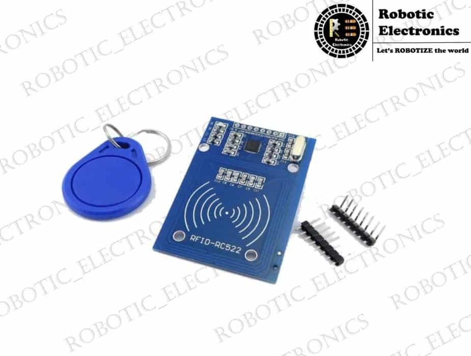
Interfacing Arduino with RFID Module In this article interfacing of RFID module with Arduino is explained, RFID means RADIO FREQUENCY IDENTIFICATION which is invented to track and find the tagged or tag containing objects. RFID works on the principle of ELECTROMAGNETIC INDUCTION. An RFID system consists of two main components which are 1. TRANSCEIVER OR READER 2. TRANSPONDER OR TAG The reader consists of a radio frequency module and antenna which generates high-frequency electromagnetic radiation or field Whereas tag is a passive device which means it does not have any battery in it. The tag receives the high-frequency electromagnetic field and some of this radiation is entering into rectifier circuit stores in capacitors as energy. This energy is used as a power supply to the RFID tag. And the remaining radiation is transmitted by the transmitter which is present in TRANSPONDER OR RFID TAG.     Specifications of RFID Module: The operating frequency range of the RFID module is up to 13.56MHz The operating supply voltage of the RFID module is 2.5V to 3.3V The maximum operating current that can be drawn from the reader is 13-26mA There are 8 pins in the RFID reader and the pins are VCC: This pin is the power supply pin. The power that can be given to this pin is 2.5V to 3.3V.  You can connect it to 3.3V output from your Arduino. Remember connecting it to a 5V pin will likely destroy your module. RST:  It is reset pin and set data from the beginning. GND:  GND is the ground pin and is connected to the GND of Arduino. IRQ: It is an interrupt pin that can alert the microcontroller when the RFID tag comes into its vicinity. MISO/SCL/Tx: pin acts as Master-In-Slave-Out when the SPI interface is enabled, acts as a serial clock when the I2C interface is enabled and acts as serial data output when UART interface is enabled. MOSI: It is SPI (SERIAL PERIPHERAL INTERFACE) input to the RC522 Module. SCK (Serial Clock): It accepts clock pulses provided by the SPI bus Master i.e. Arduino. SS/SDA/Rx: this pin acts as Signal input when the SPI interface is enabled, acts as serial data when the I2C interface is enabled and acts as serial data input when the UART interface is enabled. This pin is usually marked by encasing the pin in a square so it can be used as a reference for identifying the other pins. CONNECTING THE RFID MODULE WITH ARDUINO The RFID module connection to the ARDUINO is discussed in the following steps: There will be 8 pins in the RFID module as we discussed earlier. Initially, the VCC pin of the RFID module is connected with the VCC (3.3V) pin of the ARDUINO by using the male to female jumper wire. Then the ground (GND) pin of the RFID module is connected with the GND  pin of the ARDUINO by using the male to female jumper wire. And then RST pin is connected to the digital pin of the ARDUINO and that is pin#5 IRQ Pin is left unconnected because the library which is used in ARDUINO IDE is unsupported. And remaining pins like MOSI connected with pin#11, MISO connected with pin#12, SCK connected with pin#13, SS connected with pin#10. Now the power supply is given to the ARDUINO for the functioning of ARDUINO development and an RFID module. The complete set up of the interfacing of ARDUINO with the RFID module is done perfectly. WORKING : A Reader consists of a Radio Frequency module and an antenna which generates a high-frequency electromagnetic field. The tag is usually a passive device, it means it doesn’t contain a battery. But it contains a microchip that stores and processes information, and an antenna to receive and transmit a signal. The information that is stored on a tag, it is placed close to the Reader (does not need to be within direct line-of-sight of the reader). A Reader generates an electromagnetic field which causes electrons to move through the tag’s antenna and subsequently power the chip. The powered chip inside the tag then responds by sending its stored information back to the reader in the form of another radio signal. This is called backscatter. The backscatter or change in the electromagnetic/RF wave is detected and interpreted by the reader which then sends the data out to a computer or microcontroller. ARDUINO PROGRAM : #include #include   #define SS_PIN 10 #define RST_PIN 9 MFRC522 mfrc522(SS_PIN, RST_PIN);   // Create MFRC522 instance.   void setup() {   Serial.begin(9600);   // Initiate a serial communication   SPI.begin();  // Initiate  SPI bus   mfrc522.PCD_Init();   // Initiate MFRC522   Serial.println(“Approximate your card to the reader…”);   Serial.println();   } void loop() {   // Look for new cards   if ( ! mfrc522.PICC_IsNewCardPresent())   { return;   }   // Select one of the cards   if ( ! mfrc522.PICC_ReadCardSerial())   { return;   }   //Show UID on serial monitor   Serial.print(“UID tag :”);   String content= “”;   byte letter;   for (byte i = 0; i < mfrc522.uid.size; i++)   {   Serial.print(mfrc522.uid.uidByte[i] < 0x10 ? ” 0″ : ” “);   Serial.print(mfrc522.uid.uidByte[i], HEX);   content.concat(String(mfrc522.uid.uidByte[i] < 0x10 ? ” 0″ : ” “));   content.concat(String(mfrc522.uid.uidByte[i], HEX));   }   Serial.println();   Serial.print(“Message : “);   content.toUpperCase();   if (content.substring(1) == “BD 31 15 2B”) //change here the UID of the card/cards that you want to give access   { Serial.println(“Authorized access”); Serial.println(); delay(3000);   }    else   { Serial.println(” Access denied”); delay(3000);   } } CONCLUSION: Finally, the interfacing of ARDUINO with the RFID module is done successfully. In this way, the RFID module is connected with ARDUINO and these projects have a vast number of applications in our daily life.

UNMANNED AERIAL VEHICLES

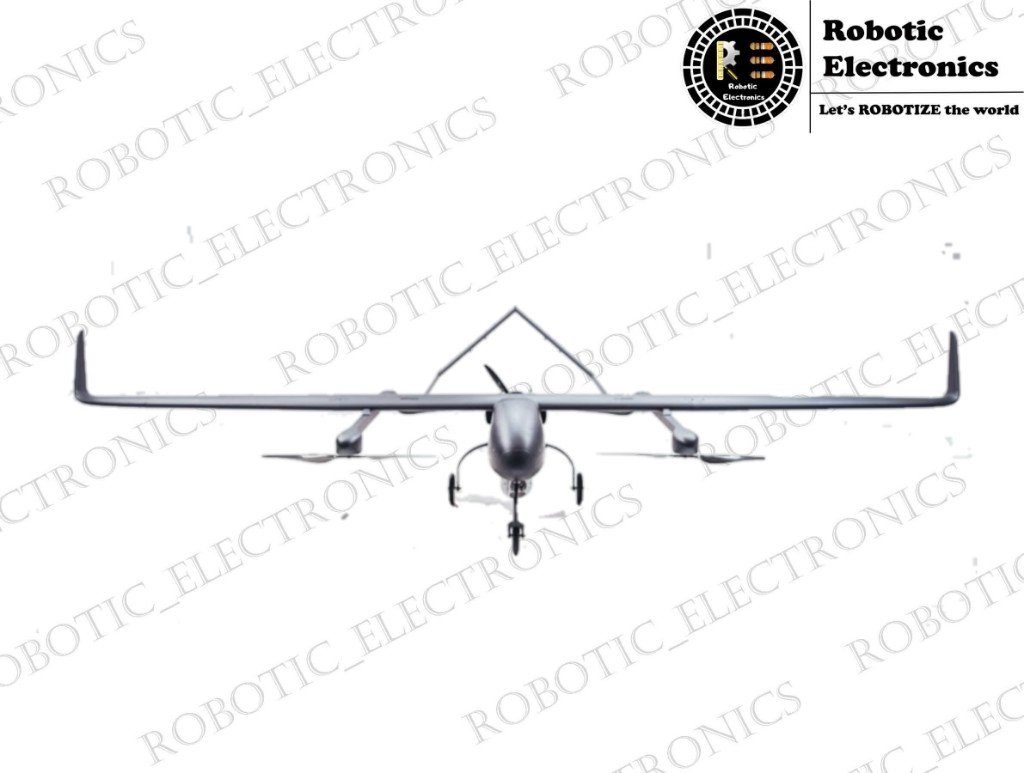
UNMANNED AERIAL VEHICLES INTRODUCTION: Unmanned aerial vehicles (UAVs) commonly known as “DRONES”. A drone is an aircraft, which can fly without a human pilot. UAVs are the components of the Unmanned Aerial System (UAS). Which also includes other components like a ground-based controller and a communication system to link the two. These systems include UAVs which are remote-controlled by human and autonomously controlled (with predefined route).  Initially, these drones are developed for military applications, later there use is rapidly expanded to other fields like agricultural, commercial, surveillance, product deliveries, and photography. EVOLUTION OF DRONES In 1849, when Venice was fighting for its independence from Austria. Then Austria used an unmanned balloon loaded with explosives. Although balloons are not considered as UAVs in the present scenario. Later In 1915, During the battle of Neuve Chapelle British military used aerial photography to capture about 1500 sky view of german trench fortification in the region. During the 1st World War, the first pilotless radio-controlled aircraft was used by the US Army. In 1918 US Army experimented “Kettering Bug which was unmanned flying bomb aircraft that was never used in combat During World War 2, the US army developed a first remotely controlled aircraft called “The Radioplane OQ2”. Which was developed by Reginald Denny and his partners? They have manufactured nearly 1500 drones for the Army during WW2. During the 1930s, US Army experimenting on radio-controlled aircraft and in 1937 they created a “Curtiss N2C-2” drone. It was remotely controlled from another aircraft called TG-2. During the war of Israel and Syrian, Israel used many UAVs and manned aircraft to defeat Israel forces. In 1986, an aircraft called “RQ2 Pioneer”, was created by the US and Israel. Which was a medium-sized reconnaissance aircraft? In 2000 the U.S developed a UAV called “Predator Drone” in Afghanistan to hunt Osama Bin Laden.   TYPES OF DRONES: UNMANNED AERIAL VEHICLES can be classified on different basis like: Types of drones based on aerial platforms: MULTI ROTOR DRONES These are the most common type of drones which used for most applications like aerial photography, aerial cinematography, etc. These can easily be manufactured and they are cheaper compared to other drones.  Multi drones are further classified based upon the number of rotors. They are TRICOPTER: Which has 3 rotors QUADCOPTER: Which has 4 rotors. HEXACOPTER: Which has 6 rotors. OCTOCOPTER: Which has 8 rotors.                                                                                 As per the aerodynamics, an increase in the no of rotors increases the spin of an object. So quadcopters are more stablethanthe octocopters.  The main drawback of the Multi-Rotor Drone is it’s low flying time. Most of the multirotor drones have the capability of 20 to 30 min of flying time SINGLE ROTOR DRONES Single rotor drones are similar in design to the helicopter. They have only one rotor on top and one small rotor at the tail to control heading. Single rotor drones have more efficiency than multi-rotor drones. As per the aerodynamic, single rotor drones are more stable than multi-rotor drones. These drones have more flying time and can hover with a heavy load. They can be powered with a gas motor for longer endurance. Main drawbacks of single rotor drones: They are more expensive. Difficult to control. Dangerous because of the heavy spinning blade. These are mostly used in the LIDAR laser scan  FIXED WING DRONES A Fixed Wing Drone uses a rigid wing like an airplane to provide the lift rather than rotors which provide vertical lift.So these drones use energy during glide only but not to hold themselves up in the air. These drones can stay in the air for 16 hours or more if they use gas engines as their power source. Advantages of fixed-wing drones are They can cover greater distances compared to the other two types of drones. Fixed-wing drones can continue flying and land safely without power. The fixed-wing drone is more stable than other drones. The drawback of fixed-wing drones are These drones are more costly than multi-rotor drones. These drones can’t hover at one place like MRD and SRD. So these are not used for aerial photography and aerial cinematography. The launcher is needed to get a drone into the air Difficult to land the drone. These drones are used in industries, agriculture sector, mapping, surveillance. FIXED WING HYBRID DRONES There is various type of drones under development some of which have a fixed-wing design with vertical lift motors on it. Some have rotors on their tail which just looks like an airplane. Benefits of fixed-wing hybrid drones are Greater endurance. Ability to cover a longer distance with high speed. Cover more ground compared to MRDs. It can take-off and land vertically. The drawback of fixed-wing hybrid drones are Not perfect at either hovering or forward flight. Still under development. Used mostly for military operation where it is difficult for a manned aircraft to reach and in many other fields. Types of drones based on their size get a drone into the air VERY SMALL DRONE These UNMANNED AERIAL VEHICLES are very small ie,up to 50cm. SMALL DRONE The size of these drones is less than 2 meters. These are the size of mostly used drones. These drones can be handled by a person MEDIUM DRONE Smaller than the size aircraft.  Two persons are needed to carry. LARGE DRONE These are replacements for the manned aircraft. Mostly used for military or surveillance purposes. Types drones based on their range: VERY CLOSE RANGE These are mostly used for aerial photography, as a toy for kids and many commercial purposes. They fly upto 5km with a fly time of 20 to 45 minutes. CLOSE RANGE They can fly up to the range of 50km with a flight time of 1 to 6 hours. These are

Arduino with Servo Motor

Arduino with Servo Motor Introduction In this module, we are going to discuss Arduino interfacing with the servo. It is an electric device used for precise control of angular rotation. It is used in various applications like a robotic arm. The rotation angle of the servo motor is controlled based on the PWM signal. By varying the width of the PWM signal, we can change the rotation angle and direction of the motor. Inside of the servo motor Servos consist of circuitry which receives the command and is responsible for their control at a particular angle. The entire circuit is placed inside the motor along with the motor gear. The servo motor is rotated based on the signal from the circuit and depending on the angle.   To understand the working of the servo motor the internal structure has to be analyzed. In the servo motor different parts are shown in the image below. The motor is attached accordingly by using the gear mechanics. The potentiometer’s resistance changes with the rotation of the motor. The rotation of the motor will depend on the PWM signal     The servo motor consists of VCC, GND, SIGNAL pins. Electrical pulses or signals are given through the signal wire, which determines the movement of the servo motor. Servo motors can rotate in 90 or 180 degrees. The rotor of the servo motor will move in the position based on the signal. The servo motor speed is dependent on the angle. The motion of the motor is controlled based on the distance of the destination. This is called proportional control. Connecting the servo with Arduino The red wire in the servo is VCC pin connect it to 5v of Arduino The brown wire is ground pin connect it to the ground of Arduino Orange is a signal wire connected to  pin 10 Arduino program for servo #include  <Servo.h> //including the servo library Servo myservo;      //including a variable for servo named sg90 int servo_signal = 10; void setup() { myservo.attach(servo_signal);  //Giving the command to arduino to control pin 10 for servo } void loop() { myservo.write(0); // moving the servo at 0 degree delay(1000); myservo.write(45); // moving the servo at 45 degree delay(1000); myservo.write(90); // moving the servo at 90 degree delay(1000);    // wait for 1 second myservo.write(135); // moving the servo at 135 degree delay(1000); myservo.write(180);   // moving the servo at 180 degrees delay(1000);    // wait for 1 sec } Working of servo When the commands are given in the Arduino, it sends signal information through the signal pin to the servo according to the signal it generates the respective resistance inside the servo by which, the servo can rotate and fix at desired angle .a signal from the shaft is taken through the potentiometer to analyze angle .this potentiometer feedback mechanism is used for the precise output of servo. Hence bye wishes it gains a high angular rotational accuracy. Explanation of code While working with Servo we have to include a new library in the code.it includes all the directories and functions required for the operation of the servo.   Firstly we have to give a name for our servo ( helps more if we use more than one servos in the project) [Servo myservo; ].where myservo is the name given to it.   Next, we have to declare a digital pin for signal, we are using pin number 10 in the code.   [myservo.attach(servo_signal);  ] here we use  servoname.attach(signalpin) command to declare which pin is connected to the signal wire of servo.   [myservo.write(angle)] is used to make the servo to rotate in the desired angle. Where angle is the attribution that we have to set according to our requirement.   Conclusion   Hence we have discussed the structure, working principle and code keywords that are used to operate the servo and this is the end of this tutorial arduino with servo motor.