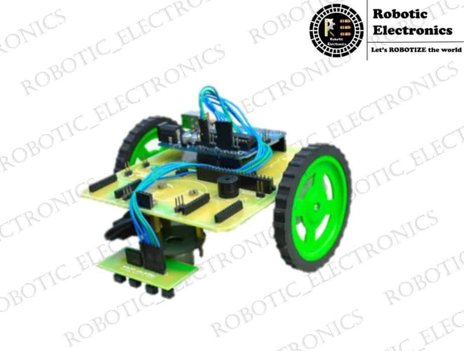
Arduino

Arduino with Speaker

INTERFACING SPEAKER WITH ARDUINO This article is about to explain how to play music with a speaker or a 5v buzzer. Here in this we use a Arduino uno board to play coffin dance music with a 4Ω speaker. Use the source code in the article (do not alter it may cause different output)  upload it to Arduino uno using an Arduino IDE platform. Basically to run a speaker using any microcontroller, the digital signal ( signal from microcontroller ) should be converted to analog from ( sound wave ) . Aim: To play music with a speaker using Arduino UNO board.    Materials Required: Arduino uno or any Arduino board, Bread Board, Jumper Wire/Connecting Wire, Transistor bc557, Speaker 4 Ω 3W . Step-1: Connecting with Arduino Connections for the project connect Arduino to computer, use speaker instead of buzzer. In the below image a buzzer is used instead of speaker. make sure the connection are made as per the diagram. Step-2: After completing the basic connections as per diagram then we want to upload the source code to the uno board using the Arduino IDE. The code for the following is, Main Code:  After this add new tab in Arduino IDE and add the below code to attach note library for sounds,                      Pitches.h Code: NOTE name the new tab created as “pitches.h”and paste the below code Final Setup:  Conclusion:               Using this project we can play sound with speaker without any sound amplifier or anything to make electrical signal to sound for speakers and buzzer. Also read about 8051 microcontroller

How to use Arduino Analog Input – Theory and Practical

Arduino Interface LM35.jpg

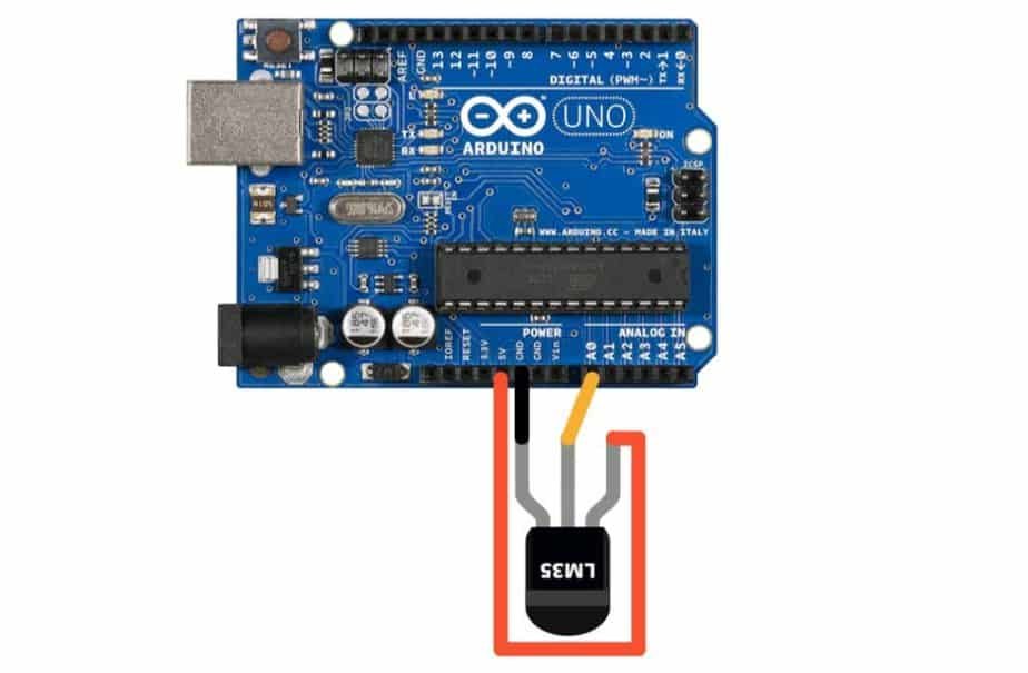
How to use Arduino Analog Input In this tutorial, you will learn about How to use Arduino Analog Input along with the practice example. Analog input is to get data from analog sensors into our Arduino. Since most of the sensors are analog, it is quite important to get our basics clear. Let’s begin with theory: – First of all, we need to understand what an analog signal is. This is probably something which you might have studied in school. A digital signal is one which, at any point of time is either HIGH or LOW. An analog signal is one which varies continuously with time, as you can see in above picture. Now, let’s talk about analog sensors As you can see in the above infographic, a sensor (or technically, a transducer) is a device that converts any phenomenon (like temperature, light, moisture etc.) into electrical signals. In case of Arduino, this analog signal has to be fed through analog pins, into an ADC, to get the sensor values for processing. I will explain it in a moment. Arduino, as you already know is a microcontroller, but actually, Atmega328p, an IC is the brain of Arduino Uno. Atmega328p has a 10 bit ADC, which processes the analog signals. Let us try to understand ADC first. Analog to Digital converters, or commonly known as ADCs, are circuits, which convert analog signals to digital signals. Since ADCs are very broad topic, we will only see ADC of Arduino. Atmega328p has a 5v 10 bit ADC, which simply means that it generates a number between 0 – 1024 depending on input voltage 0-5 volts. The above infographic is quite self-explanatory. The ADC generates a value, based on the input signal that reflects the data from the sensor. One should note that the value from ADC is not the actual sensor value. To get the actual sensor value, one has to calibrate the sensor. Calibration of sensor is sensor specific, there is not general calibration, and is usually given by the manufacturer in the datasheet. Note that Arduino Uno has 6 analog pins, meaning you can use up to 6 sensors. That was all in theory, let us see how it works in practice. Time to get our hands dirty: – We will use LM35 temperature sensor by Texas Instruments, it is the most commonly used temperature sensor that measures temperature in the range   -55 C to 150 C. It is a three terminal device. You can easily find it in any electronics store and is usually included in most of the Arduino educational kits. Here’s how it looks- It is an analog sensor. It is a three-legged device, as one can see:- Vs, GND and Vout. Vs and GND pins are to power the circuit. You can connect to supply of up to 30 volts. Arduino has 5v pins to do this job. Vout is the output pin and has to be connected with A0 pin of Arduino (or any other analog pin). The signal generated by LM35 varies linearly with temperature. It is 10mV per degree rise/fall in temperature. Let’s see the circuit, it is a very simple one, connect the pins as described. Circuit Diagram Code float vout;  //temporary variable to hold sensor reading void setup() { pinMode(A0,INPUT); //A0 is pin number, INPUT is self-explanatory Serial.begin(9600); } void loop() { vout=analogRead(A0); //This function reads the value of ADC at pin A0.  vout=(vout*500)/1023; Serial.print(“Temperature =  “); Serial.print(vout); Serial.println(); delay(1000); //Getting temperature every second is a good idea! } You can copy paste the code in your Arduino IDE and upload the sketch. Code Explanation If you are more curious about the code (which you should be), I will explain the critical parts. pinMode(A0, INPUT) :- Defines that pin A0 is going to be used for input. vout=analogRead(A0) :- This function returns the value of ADC at pin A0. As discussed before, it returns a value between 0 and 1024 depending on temperature range of sensor (0C to 155C). vout = (vout*500)/1023 :- Don’t worry about this, here temperature is calculated out of ADC values based on calibration factor (10mV/C here). You can usually find this by a simple search. Once you have uploaded the sketch, therefore you can open serial monitor (ctrl+shft+M) to see the output. Conclusion Pro Tip: To verify if the sensor is working, blow on the sensor, you’ll observe the change in temperature. I hope that you are clear with the tutorial. If you have any queries, please feel free to ask in the comment section below.

Interfacing of HC-SR04 Ultrasonic Sensor with Arduino Uno

INTERFACING OF ARDUINO UNO WITH ULTRASONIC SENSOR  Complete arduino kit for beginners This tutorial is about the interfacing of the Arduino UNO board with HC-SR04 commonly known as ultrasonic sensor and code to run the sensor and obtain the output from the sensor accordingly. List of the components Arduino uno board HC-SR04 ultrasonic senso Bread board Jumper wires Working principle of the ultrasonic sensor  The working is very simple, the trigger pin of the HC-SR04 emits and transmits a high-frequency pulse. The HC-SR04 uses high frequency sound waves to find this distance, a kind of echolocation. If we need a machine to know about an obstacle in its path,we should  use an ultrasonic sensor. The HC-SR04 sensor echo pin senses the reflection.  Pins Of Ultrasonic Sensor HC-SR04 Ultrasonic sensor has four pins. Pin 1=Vcc=5v input  voltage to power the sensor.  Pin 2=trig pin=input pin for sending ultrasonic waves. Pin 3=echo pin=output pin. Pin 4=ground pin=it should be connected to the ground. Explanation The Arduino UNO has a micro-controller that reads data from various inputs and can compute it according to the programming code. Arduino Uno has 14 digital input & output pins and also 6 analog pins. The Arduino Uno power supply can be done with the help of a usb cable or an external power supply. The suggestion voltage range power is 9 to 12 volts. The circuit of the Arduino and distance sensor consists of  three parts. (i) Micro-controller (ii) Transmitter  (iii) Receiver Microcontroller It controls the timing and sending of pulses.  It receives the signal from the receiver as an interrupt, it also controls the frequency and speed of the sound wave generated and also record’s the time taken to receive the reflected wave. Transmitter The transmitter of the HC-SR04 emits high frequency sound waves. Receiver It receives the ultrasonic wave reflected by the object in front of the sensor  Pin Diagram Connect the VCC pin of the distance sensor(HC-SR04) with the 5V VCC output pin of the Arduino Uno board. Now, connect the trigger of HC-SR04 to digital pin 11 on Arduino board Then connect the echo pin of HC-SR04 to digital pin 12 on Arduino board. Finaly, Connect the ground pin of the ultrasonic sensor to Arduino’s ground pin. Code Result Upload the code to the Arduino UNO board and the distance of the object can be seen on the serial monitor screen. For any queries, the comment box is always open for you.

OBSTACLE AVOIDING ROBOT

OBSTACLE AVOIDING ROBOT What are we going to build? We will build a simple obstacle avoiding robot that will avoid obstacles which are in its path. There can be two possible robots that can be built:- 1. A simple robot with no rotation of the distance sensor. 2. A mediocre robot with the rotation of the distance sensor. Let’s gather the components needed:- 1. Arduino mega. (or any other Arduino i.e Arduino Nano or Arduino UNO). 2. L298N Dual H Bridge Stepper Motor Driver. 3. DC hobby BO motors.   4)HC-SR04 Ultrasonic Distance Measuring Sensor Module 5)9v battery 6)Robot chassis Obstacle avoiding robot Circuit Diagram. Connections of Ultrasonic sensor – 1.         VCC – VCC terminal of Arduino. 2.         GND – GND terminal of Arduino. 3.         Trigpin – digital pin 9 on Arduino. 4.         Echo pin – digital pin 10 on Arduino. Connections of L298N – 1.          +12V – Positive terminal of the battery. 2.         GND – a)GND of Arduino b)Negative terminal of the battery. 3.         Input terminal 1 – Pin 4 4.         Input terminal 2 – Pin 5 5.         Input terminal 3 – Pin 6 6.         Input terminal 4 – Pin 7 7.         The output terminal 1 – Positive of the first motor. 8.         The output terminal 2 – Negative of the first motor. 9.         The output terminal 3 – Positive of the second motor. 10.  The output terminal 4 – Negative of the second motor. Code Select the appropriate board in the Arduino ide Select the com port to which the Arduino board is plugged into and upload the code Obstacle avoiding Robot Explanation First, we will be finding the distance between the robot and its surroundings. For this, we have the ultrasonic sensor module which can measure distances from 2cm to 400cm of non-contact measurement functionality with a ranging accuracy that can reach up to 3mm. The ultrasonic sensor emits a high-frequency sound pulse and calculates the distance depending upon the time taken by the echo signal to travel back after reflecting from the desired target. The speed of sound is 341 meters per second in air, knowing this we get the duration of the pulse from the pulse function and we divide it by 2 since the duration output not only contains time taken for the pulse to hit the obstacle but also contains the time taken for the high-frequency pulse to return. This corresponds to about 29.412µs (microseconds) per centimeter. To measure the distance the sound has traveled we use the formula: Distance = (Time x SpeedOfSound) / 2.The better way to get the distance as centimetres is to use the formula: Centimetres= ((Microseconds / 2) / 29). After getting the distance we will use the distance to perform obstacle avoidance by sending commands from the microcontroller to the H-bridge motor driver. The robot will move forward only if the distance between the obstacle and robot is greater than 20 centimeters else it’s going to keep on turning left until the robot finds a path with no obstacles up to 20 centimeters of range. But why do we need a motor driver? Motor drivers act as an interface between the motors and the control circuits. The motor requires a high amount of current whereas the controller circuit works on low current signals. So the function of motor drivers is to take a low-current control signal and then turn it into a higher-current signal that can drive a motor.

Line Follower Robot

Line Follower Robot Welcome to robotic electronics. Here, we begin with a Line Follower Robot. Once, a person in England thought of making a  mobile bot as a line follower robot and prepared an Electro-Light-Sensitive-Internal-External(ELSIE) in 1953, which follows a light source using a mechanical feedback system with no intelligence. There kickoff the evolution of our Line Follower bot. DEFINITION  A line follower bot is a mobile bot that follows a given white or black line over a white or black background by sending and receiving Infra-Red rays by using IR sensors. These are used in the factories to carry the finished products to the whare house with no human intervention. And now are you interested in building one! Here we go.. One can readily build a Line Follower Robot in short LFR by using the following elements 1.Chassis: Chassis is the body of the bot, we can use a metal chassis or a wooden board to fasten all other elements 2.Motors: The motor is a prime mover or actuator mainly used for the motion of the bot. We can use center shaft motor, N120 motor, or a basic operation (BO) motor. 3.Wheels:            Wheels of different sizes are available in the market, we can use wheels of small size for easy movement of the bot, we can use a freewheel in the front 4.IR sensors: IR sensor is the main component in the LFR. We can use an IR array of individual IR sensors for this purpose. One can make a basic LFR by 3 IR sensors. 5.MicroController: It links the IR sensors to the actuators ie; motors. We can use an Arduino Uno or Arduino Nano for this LFR. 6.Battery:                The battery is the power source for the MC, we can use a lithium-ion battery or a lithium-polymer battery for less weight of the bot. We can also use a lead-acid battery. 7.Motor driver:   A Motor driver is an element that provides the required current input for the motors. Arduino output will be the Motor driver’s input. L298n is a motor driver used to control two motors, with a heat sink.  8.Jumper wires: A jumper wire is used for the current to flow from the battery to other elements. 9.Fasteners: Fasteners such as double tape, motor clamps, screws, nuts, and bolts are needed. PROCESS OF MAKING A LINE FOLLOWER ROBOT First, take the chassis and attach the two motors on both sides by using clamps with screws. Then attach the wheels to the motor shafts by screw. Place the Micro Controller on the chassis and fasten it by screws Place the IR sensors in the front by leaving 3 mm gap between the ground If three IRs are used then place one in the middle and other two at sides Place the Motor driver, Battery at the designed place on the chassis Place the freewheel in the front bottom part seeing the body is parallel to the ground. Now start connections of the IR sensors to the Arduino, Motors to the  Motor driver then to the Arduino, Battery to the Motor driver. Now the bot is mechanically ready for functioning. For having intelligence to follow a white or black line it needed to be coded CODING: The code goes in this way, After coding is done in your pc you need to dump it into the Arduino by using a connecting cable. CONCLUSION After checking the connections as per code you’ve made, the Line Follower Robot is ready to follow the line.

Home automation using bluetooth and Arduino

Home automation using bluetooth and Arduino In this article, I am going to tell you how to make the Home automation using bluetooth and Arduino. You can control your home appliances using your smartphone easily. These can be used in houses, apartments, hotels, etc.  I want to know how to make this project and make your home automated. Step 1: Components Required Hardware :     Arduino UNO     2 channel Relay     230V AC supply     Jumper Wires     HC05 Bluetooth Module Arduino UNO Relay bluetooth module Software :     Arduino IDE     Blynk App Step 2: Blynk Setup First of all, download the Blynk app on an Android device. Register with your device. Click on ‘create a new project Select your project name (eg: Home automation) Choose your board: Arduino UNO Choose connection type: Bluetooth And click on the create button. Hence, your project is ready to edit. An email will be sent to your mail-id. Copy the authentication code from your mail. Now, install the blynk libraries to your Arduino IDE. You have to paste the Auth token in the Arduino code. Now, your Arduino is ready to take instructions from the app. Let’s create the functions to be performed in the Blynk app. Step 3: Blynk Interface Click on add widget button to create your operations. Select the ‘Bluetooth’ widget and the 2 buttons to control 2 devices in your home. If you want to control more number of devices you can add buttons to your requirement. Now, customize the button settings to acts as a switch. Select the digital pin in the Arduino that you are using to control specific appliances. After making the necessary connections, customize Bluetooth settings to connect to your HCO5 device.Step 4: Connections The connections are very simple. There are 6 pins for HCO5 from which we use only 4 pins (TX, RX, VCC, GND). The TX and RX pins are connected to 10,11 pins respectively. VCC is connected to 3.3v pin on Arduino. GND pin is connected to the GND pin of Arduino.   Note1: Take care that the pins TX and RX of the Bluetooth are not connected to Arduino during the uploading of the code. After the code is uploaded, we can connect them to their respective pins.   Relay is simply an Electronic switch used to control electrical appliances. A 2- channel relay has 4 pins to be connected to Arduino (VCC, GND, D0, D1). The VCC and GND are connected to the respective pins of Arduino. With the pins D0, D1 we can control 2 appliances of our home. Let these pins to be connected to D2, D3 pins of Arduino since we used the same pins for buttons in BLYNK app.  The other side of the relay has 3 connections namely NC (Normally Connected), COM ( common), and NO (Normally Open). Connect the positive terminal of the lamp to the positive terminal of the AC supply. Now break the negative terminal of the lamp and connect one end to COM pin and another end to NO pin of the relay. Now, The circuit is ready to be executed. Step 5: Code The Arduino code requires some standard libraries to perform this project namely “blynk” And “SoftwareSerial.h”   The Arduino code is as follows : Note2: Check whether the libraries are successfully installed in your software.After completion of coding and using the Auth Token in the code, we have to setup Arduino IDE.go to  TOOLS / BOARD /GENUINE UNO andTOOLS/ PORT/COM_Now your software setup is complete. Upload your code (refer Note 1) and you are ready to test your project.  Conclusion :  Hence, the prerequisite required to make the project Home Automation using Bluetooth is ready to be followed. As it doesn’t require the Internet, It can be used anywhere in the world.

Arduino Weather Station

Arduino Weather Station We people always listen to weather forecasting to know the weather conditions around us …here I will explain how to make simple Arduino Weather Station sense temperature and humidity using DHT11 sensor and Arduino, the sensed data will be displayed on LCD. How To Make Simple Arduino Weather Station things  required to make an Arduino based weather system: Components description: 1.DHT11 DHT11 is a humidity and temperature sensor. It can be used as the humidity sensor as we as temperature sensors. You can find the dht11 sensor of 2 types. One is with the 4 pins and the other with 3 pins. In 3 pin sensors, a 10k ohm resistor is already added inside the module. The operating voltage of this module is 3.3V. 2.Arduino UNO The Arduino Uno is a microcontroller board based on  ATmega328. It has 20 digital input/output pins,16 MHz resonators, a USB connection, a power jack, an in-circuit system programming (ICSP) header, and a reset button. It is an open-source electronics platform based on easy-to-use hardware and software. Arduino boards can read inputs and turn it into an output. 3.16×2 LCD Display An LCD (Liquid Crystal Display) screen is an electronic display module. A 16×2 LCD means it can display 16 characters per line and there are 2 such lines. In this LCD each character is displayed in a 5×7 pixel matrix. The 16 x 2 intelligent alphanumeric dot matrix display is capable of displaying 224 different characters and symbols. Steps to be followed : step 1: Connecting DTH11 with Arduino connections as follows: if you are using 4 pins DHT11 Connections are as follows Connect a 10K Ohm resistor between VCC and output pin of DHT11. DHT11 Arduino UNO Vcc 3.3V Out PIN4 (Digital) GND GND NC — if you are using  3 pins DHT11 Connections are as follows DHT11 Arduino UNO Vcc 3.3V Out PIN4 (Digital) GND GND Step2: connecting 12C LCD Display to Arduino connections as follows:    GND<—>GND     VCC<—>5V     SDA<—>A4     SCL<—>A5 Step 3: You must include DHT11 and 12C LCD libraries. Step 4: the Arduino code which is given below has to be dumped into the Arduino UNO board using a connector. Code:  LiquidCrystal_I2C lcd(0x27, 2, 1, 0, 4, 5, 6, 7, 3, POSITIVE); #define DHT11_PIN 4 DHT dht (DHT11_PIN, DHT11) ;  void setup(){ dht.begin() ; lcd.begin(16, 2); } void loop() { lcd.setCursor(0,0); lcd.print(“Temp: “); lcd.setCursor(7,0); lcd.print(dht.readTemperature()); lcd.setCursor(10,0); lcd.print((char)223); lcd.setCursor(11,0); lcd.print(“C”); lcd.setCursor(0,1); lcd.print(“Humidity: “); lcd.setCursor(9,1); lcd.print(dht.readHumidity()); lcd.setCursor(11,1); lcd.print(“%”); delay(1000); lcd.clear() ; } Working:   After connecting all the components properly and dumping the code into the Arduino, we find the values of Temperature and Humidity displaying on the LCD. Now if we bring our hand or any other object near the sensor we observe the changes in the values of humidity and temperature on LCD.   Conclusion:   Finally, the making of the simple Arduino based weather system is done and this will sense the surrounding humidity and temperature and display it in the LCD.

Touch sensor interfacing with Arduino

Touch sensor interfacing with Arduino A touch sensor is an electronic sensor that is used to detect the touch when it is touched it acts as a switch. It is used in various places like it can be used over the touch screen ( i.e group of touch sensors are used to form a touch screen ). These are also user friendly. We are going to discuss to sensors that are Capacitive touch sensor Metallic touch sensor Capacitive touch sensor The name itself says that the capacitor is involved in this touch sensor. When we touch the sensor capacitance is being induced between the person and the sensor, and the body(the figure that used to touch) and the body of the sensor act like a parallel plate capacitor and the charge is induced between the plates. The charge is taken by the sensor and it is converted to a button press. As we remove the finger the capacitance which  is developed is lost and the circuit breaks. The most commonly used capacitive touch sensor is TTP223 touch sensor Ic. The equivalent circuit diagram is given below, if we bring our tip of the finger near the module then a capacitor is built. The new capacitor is parallel to the capacitor c1, then the capacitance is increased.  The induction that is taken by the sensor as a button press.  We just take our finger near to the touch plate but not to touch Metallic touch sensor It is based on MOSFET, the gate of the MOSFET is left open and its source is connected to the operational amplifier. When the gate is touched it starts conducting also the operational invert the input threshold voltage and the operational amplifier conducts and a variable resistor is used to set the threshold value. The schematic diagram is given below     The output of the metallic sensor is I both analog and digital, the analog value depends on the charge in the MOSFET and the digital value is high when we touch and low when it is left alone. Capacitive sensor with Arduino UNO The switch will be on when the touch sensor is touched by the finger also the buzzer will produce the sound and then it is off, we can also print how many time it is touched by a small screen The touch sensor pin is connected to pin 2, the buzzer is connected to pin 9 of the Arduino Uno also both the buzzer and the sensor is powered through the 5-volt output of the Arduino regulator Source code a program is written on how the sensor to be worked int buzzer=9; int capsensor=2; void main() { Pinmode(buzzer,output); Pinmode(capsensor,input); Serial,begin(9600); } From the above code, we declared that pin 2 and 9 are capsensor and buzzer and we have given capsensor as the input and the buzzer as the output then we gave the serial number of the Arduino as 9600 in the loop the statement digitalread(capsensor)==high then it checks the touch sensor, if anything id touched to the sensor it shows high on the serial monitor of the Arduino IDE. Then the buzzer will be switched on. After a delay of 1, secondly keeps the buzzer in buzz state for 1 second. After 1 second the control jumps out of the if statement and then buzzer is turned off. The loop function runs for an infinite amount of time so whenever the sensor pad is touched a sound is produced for 1 second. Metallic touch sensor using Arduino UNO The metallic touch sensor can be interfaced in two ways both digital and analog form, for the digital interface it is same as the capacitive touch sensor   Source code Conclusion  The above-discussed information is all about interfacing Arduino with the ttp233 sensor to monitor the touch on the substance. Also, the basic information is discussed above

RADAR USING ARDUINO

RADAR USING ARDUINO  What is Arduino Radar?  Arduino Radar is a simple Radar Application using Arduino and Processing. This Arduino Radar is implemented with the help of Processing Applications.  In this article, you will know how to design a simple DIY Arduino radar.  Radar is a long-range object detection system that uses radio waves to establish certain parameters of an object like its range, speed, and position. Radar technology is used in aircraft, missiles, marine, weather predictions, and automobiles.  Even though the title says Arduino Radar, technically it is based on Sonar technology as I will be using an Ultrasonic Sensor to determine the presence of any object in a limited range.  OVERVIEW  The Arduino Radar Project is more of a visual project than it is a circuit implementation. Of course, I will be using different hardware like Arduino UNO, HC-SR04 (Ultrasonic Sensor) and Servo Motor but the main aspect is the visual representation in the Processing Application.  We will collect the information from the Ultrasonic Sensor with the help of Arduino and pass it to Processing where a simple Graphics application is implemented to mimic a Radar Screen.  HOW TO DO IT?  Components Required  Hardware  Arduino UNO   HC-SR04 Ultrasonic Sensor    TowerPro SG90 Servo Motor    Mounting Bracket for Ultrasonic Sensor (optional)    Connecting Wires    Jumper Cables    5V Power Supply    USB Cable (for Arduino)    Software  Arduino IDE  Processing Application  Circuit Diagram of Arduino Radar  The circuit diagram of this Radar is very simple as it involves very little hardware.  Illustration of circuit diagram  A radar sweeps an area to detect the objects in the range. Similarly, in the Arduino radar, we are using an ultrasonic sensor to scan for objects. To move it in our entire range we are using servo motor for the movement of the sensor.  WORKING   The basic structure of our radar is as follows  After the making connections:  Initially, upload the code to Arduino after making the connections. You can observe the servo sweeping from 00 to 1800 and again back to 00. Since the Ultrasonic Sensor is mounted over the Servo, it will also participate in the sweeping action.  Now, open the processing application and paste the above-given sketch. In the Processing Sketch, make necessary changes in the COM Port selection and replace it with the COM Port number to which your Arduino is connected to.  If you note the Processing Sketch, I have used the output display size as 1280×720 (assuming almost all computers nowadays have a minimum resolution of 1366×768) and calculated this resolution.  In the future, I will upload a new Processing sketch where you can enter the desired resolution (like 1920×1080) and all the calculations will be automatically adjusted to this resolution.  Now, run the sketch in the Processing and if everything goes well, a new Processing window opens up like the one shown below.    Graphical representation of the data from the Ultrasonic Sensor is represented in a Radar type display. If the Ultrasonic Sensor detects any object within its range, the same will be displayed graphically on the screen.    Code  There are two codes for this project: one for the Arduino UNO and the other for the Processing.  Arduino Code  The code for Arduino UNO is given below.      Object detection   After writing the code in both Arduino and processing we are ready to go for object detection. The output in the processing is as follows  Graphical representation of the data from the Ultrasonic Sensor is represented in a Radar type display. If the Ultrasonic Sensor detects any object within its range, the same will be displayed graphically on the screen.