Arduino

Interfacing Arduino with RFID Module

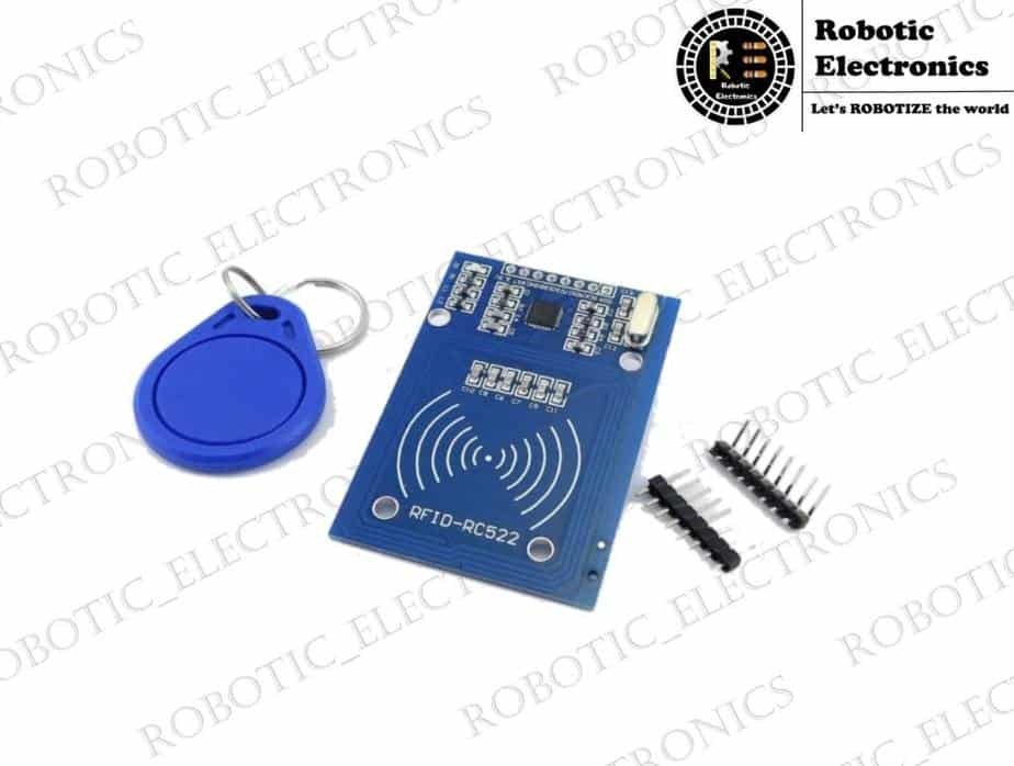
Interfacing Arduino with RFID Module In this article interfacing of RFID module with Arduino is explained, RFID means RADIO FREQUENCY IDENTIFICATION which is invented to track and find the tagged or tag containing objects. RFID works on the principle of ELECTROMAGNETIC INDUCTION. An RFID system consists of two main components which are 1. TRANSCEIVER OR READER 2. TRANSPONDER OR TAG The reader consists of a radio frequency module and antenna which generates high-frequency electromagnetic radiation or field Whereas tag is a passive device which means it does not have any battery in it. The tag receives the high-frequency electromagnetic field and some of this radiation is entering into rectifier circuit stores in capacitors as energy. This energy is used as a power supply to the RFID tag. And the remaining radiation is transmitted by the transmitter which is present in TRANSPONDER OR RFID TAG.     Specifications of RFID Module: The operating frequency range of the RFID module is up to 13.56MHz The operating supply voltage of the RFID module is 2.5V to 3.3V The maximum operating current that can be drawn from the reader is 13-26mA There are 8 pins in the RFID reader and the pins are VCC: This pin is the power supply pin. The power that can be given to this pin is 2.5V to 3.3V.  You can connect it to 3.3V output from your Arduino. Remember connecting it to a 5V pin will likely destroy your module. RST:  It is reset pin and set data from the beginning. GND:  GND is the ground pin and is connected to the GND of Arduino. IRQ: It is an interrupt pin that can alert the microcontroller when the RFID tag comes into its vicinity. MISO/SCL/Tx: pin acts as Master-In-Slave-Out when the SPI interface is enabled, acts as a serial clock when the I2C interface is enabled and acts as serial data output when UART interface is enabled. MOSI: It is SPI (SERIAL PERIPHERAL INTERFACE) input to the RC522 Module. SCK (Serial Clock): It accepts clock pulses provided by the SPI bus Master i.e. Arduino. SS/SDA/Rx: this pin acts as Signal input when the SPI interface is enabled, acts as serial data when the I2C interface is enabled and acts as serial data input when the UART interface is enabled. This pin is usually marked by encasing the pin in a square so it can be used as a reference for identifying the other pins. CONNECTING THE RFID MODULE WITH ARDUINO The RFID module connection to the ARDUINO is discussed in the following steps: There will be 8 pins in the RFID module as we discussed earlier. Initially, the VCC pin of the RFID module is connected with the VCC (3.3V) pin of the ARDUINO by using the male to female jumper wire. Then the ground (GND) pin of the RFID module is connected with the GND  pin of the ARDUINO by using the male to female jumper wire. And then RST pin is connected to the digital pin of the ARDUINO and that is pin#5 IRQ Pin is left unconnected because the library which is used in ARDUINO IDE is unsupported. And remaining pins like MOSI connected with pin#11, MISO connected with pin#12, SCK connected with pin#13, SS connected with pin#10. Now the power supply is given to the ARDUINO for the functioning of ARDUINO development and an RFID module. The complete set up of the interfacing of ARDUINO with the RFID module is done perfectly. WORKING : A Reader consists of a Radio Frequency module and an antenna which generates a high-frequency electromagnetic field. The tag is usually a passive device, it means it doesn’t contain a battery. But it contains a microchip that stores and processes information, and an antenna to receive and transmit a signal. The information that is stored on a tag, it is placed close to the Reader (does not need to be within direct line-of-sight of the reader). A Reader generates an electromagnetic field which causes electrons to move through the tag’s antenna and subsequently power the chip. The powered chip inside the tag then responds by sending its stored information back to the reader in the form of another radio signal. This is called backscatter. The backscatter or change in the electromagnetic/RF wave is detected and interpreted by the reader which then sends the data out to a computer or microcontroller. ARDUINO PROGRAM : #include #include   #define SS_PIN 10 #define RST_PIN 9 MFRC522 mfrc522(SS_PIN, RST_PIN);   // Create MFRC522 instance.   void setup() {   Serial.begin(9600);   // Initiate a serial communication   SPI.begin();  // Initiate  SPI bus   mfrc522.PCD_Init();   // Initiate MFRC522   Serial.println(“Approximate your card to the reader…”);   Serial.println();   } void loop() {   // Look for new cards   if ( ! mfrc522.PICC_IsNewCardPresent())   { return;   }   // Select one of the cards   if ( ! mfrc522.PICC_ReadCardSerial())   { return;   }   //Show UID on serial monitor   Serial.print(“UID tag :”);   String content= “”;   byte letter;   for (byte i = 0; i < mfrc522.uid.size; i++)   {   Serial.print(mfrc522.uid.uidByte[i] < 0x10 ? ” 0″ : ” “);   Serial.print(mfrc522.uid.uidByte[i], HEX);   content.concat(String(mfrc522.uid.uidByte[i] < 0x10 ? ” 0″ : ” “));   content.concat(String(mfrc522.uid.uidByte[i], HEX));   }   Serial.println();   Serial.print(“Message : “);   content.toUpperCase();   if (content.substring(1) == “BD 31 15 2B”) //change here the UID of the card/cards that you want to give access   { Serial.println(“Authorized access”); Serial.println(); delay(3000);   }    else   { Serial.println(” Access denied”); delay(3000);   } } CONCLUSION: Finally, the interfacing of ARDUINO with the RFID module is done successfully. In this way, the RFID module is connected with ARDUINO and these projects have a vast number of applications in our daily life.

Arduino with Servo Motor

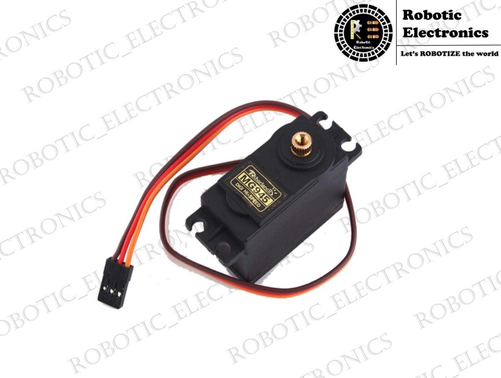
Arduino with Servo Motor Introduction In this module, we are going to discuss Arduino interfacing with the servo. It is an electric device used for precise control of angular rotation. It is used in various applications like a robotic arm. The rotation angle of the servo motor is controlled based on the PWM signal. By varying the width of the PWM signal, we can change the rotation angle and direction of the motor. Inside of the servo motor Servos consist of circuitry which receives the command and is responsible for their control at a particular angle. The entire circuit is placed inside the motor along with the motor gear. The servo motor is rotated based on the signal from the circuit and depending on the angle.   To understand the working of the servo motor the internal structure has to be analyzed. In the servo motor different parts are shown in the image below. The motor is attached accordingly by using the gear mechanics. The potentiometer’s resistance changes with the rotation of the motor. The rotation of the motor will depend on the PWM signal     The servo motor consists of VCC, GND, SIGNAL pins. Electrical pulses or signals are given through the signal wire, which determines the movement of the servo motor. Servo motors can rotate in 90 or 180 degrees. The rotor of the servo motor will move in the position based on the signal. The servo motor speed is dependent on the angle. The motion of the motor is controlled based on the distance of the destination. This is called proportional control. Connecting the servo with Arduino The red wire in the servo is VCC pin connect it to 5v of Arduino The brown wire is ground pin connect it to the ground of Arduino Orange is a signal wire connected to  pin 10 Arduino program for servo #include  <Servo.h> //including the servo library Servo myservo;      //including a variable for servo named sg90 int servo_signal = 10; void setup() { myservo.attach(servo_signal);  //Giving the command to arduino to control pin 10 for servo } void loop() { myservo.write(0); // moving the servo at 0 degree delay(1000); myservo.write(45); // moving the servo at 45 degree delay(1000); myservo.write(90); // moving the servo at 90 degree delay(1000);    // wait for 1 second myservo.write(135); // moving the servo at 135 degree delay(1000); myservo.write(180);   // moving the servo at 180 degrees delay(1000);    // wait for 1 sec } Working of servo When the commands are given in the Arduino, it sends signal information through the signal pin to the servo according to the signal it generates the respective resistance inside the servo by which, the servo can rotate and fix at desired angle .a signal from the shaft is taken through the potentiometer to analyze angle .this potentiometer feedback mechanism is used for the precise output of servo. Hence bye wishes it gains a high angular rotational accuracy. Explanation of code While working with Servo we have to include a new library in the code.it includes all the directories and functions required for the operation of the servo.   Firstly we have to give a name for our servo ( helps more if we use more than one servos in the project) [Servo myservo; ].where myservo is the name given to it.   Next, we have to declare a digital pin for signal, we are using pin number 10 in the code.   [myservo.attach(servo_signal);  ] here we use  servoname.attach(signalpin) command to declare which pin is connected to the signal wire of servo.   [myservo.write(angle)] is used to make the servo to rotate in the desired angle. Where angle is the attribution that we have to set according to our requirement.   Conclusion   Hence we have discussed the structure, working principle and code keywords that are used to operate the servo and this is the end of this tutorial arduino with servo motor.

HUMIDITY SENSOR

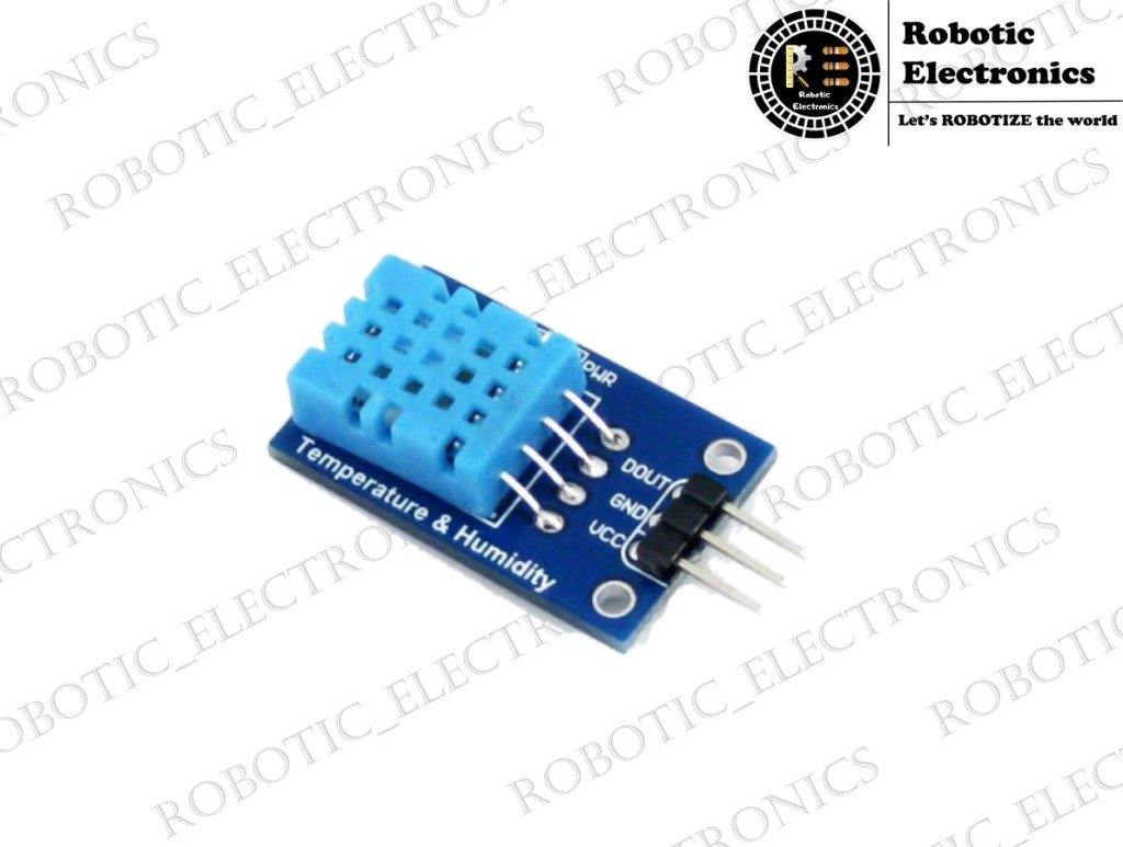
HUMIDITY SENSOR The humidity sensor is also called a hygrometer that senses, measures and gives us reports about both moisture and temperature of the air. Humidity sensor work by detecting changes that alter electrical currents or temperature within the air surrounded by us. The ratio of moisture in the air to the highest amount of moisture at a particular air temperature is called relative humidity. Relative humidity becomes an important factor when looking for comfort. There are three basic types of humidity sensors: CapacitiveResistiveThermal A capacitive humidity sensor measures relative humidity with the help of a thin strip of metal oxide between two electrodes. The metal oxide’s electrical capacity changes with the atmosphere’s relative humidity. The major application areas are Weather, commercial and industries. The capacitive type sensors are linear type and can measure relative humidity from 0% to 100%. Resistive humidity sensors utilize ions in salts to measure the electrical impedance of the atoms. As humidity changes, the resistance of the electrodes on either side of the salt medium changes. Two thermal sensors conduct electricity based upon the humidity present in the surrounding air. One sensor is enclosed in dry nitrogen while the other measures ambient air. The difference between the two sensors measures the humidity.  Each humidity sensor mentioned above has its own pros and cons.  In this, we are using DHT11 which is a capacitive humidity sensor. The DHT11 is available at low-cost, It is very convenient to use and consists of the capacitive humidity sensor and a thermistor to measure the surrounding air and gives out a digital signal on the data pins(no analog input pins is needed). Humidity measurement in industries is critical because it may affect the business cost of the product and the health and safety of the personnel. So, its huge importance of humidity sensor, especially in the control systems for industrial processes like chemical gas purification, dryers, ovens, film desiccation, paper and textile production, and food processing. In agriculture, measurement of humidity is important for plantation protection (greenhouse), soil moisture monitoring, etc. WORKING OF DHT11 As I told you before, it consists of a humidity sensing component, an NTC temperature sensor (or thermistor) and an IC on the backside of the sensor.  The humidity sensing component has two electrodes containing moisture holding substrate between them. When the humidity changes, the conductivity of the substrate changes so the resistance between these two electrodes changes. This change in resistance is measured and processed by the IC thus humidity is measured. We use the NTC temperature sensor (thermistor) to measure the temperature of the air.NTC means negative-temperature-coefficient. As the temperature increases, the resistance decreases or vice-versa. SPECIFICATIONS OF DHT11         Pin Description VCC 3.3/5V DC SUPPLY (INPUT) GND GROUND( INPUT) DOUT DATA PIN (OUTPUT) NC NO CONNECTION PIN Operating Voltage :   3.5V to 5.5V                                                                                                Operating current     :   0.3mA (measuring) 60uA (standby)                                                                      Output                      :   Serial data                                                                                                  Temperature Range  :   0°C to 50°C                                                                                                Humidity Range       :   20% to 90%                                                                                                 Resolution                :   Temperature and Humidity both are 16-bit                                                    Accuracy                  :   ±1°C and ±1% CONNECTING DHT-11 WITH ARDUINO UNO The connection of Arduino-Uno with humidity sensor(DHT 11) is done as follows: Connect the ground of Arduino-Uno with the ground of the DHT-11 sensor(It is indicated by black wire in the fig.3.) Connect the 5v pin of Arduino-Uno to the VCC of DHT-11(It is indicated by red wire in the fig.3.) Connect any one of the digital pins of Arduino-Uno with the data pin(DOUT) of DHT-11 to read values from the humidity sensor. (It is indicated by blue wire in the fig.3.) SOURCE CODE FOR INTERFACING ARDUINO-UNO WITH DHT-11 Once we upload this code into the Arduino board, the temperature and humidity values are read from the sensor and we can see it on the serial monitor. CONCLUSION                   The above-discussed information is all about interfacing Arduino with the DHT-11 sensor to monitor the humidity and temperature of the air. The basic information about the humidity sensors is also discussed.

FLEX SENSOR

FLEX SENSOR What is a flex sensor? It is very simple to understand by its name. The name indicates that the sensor is flexible and able to sense changes by the change in its flexibility i.e., bending.           A flex sensor will give values according to its bending angle and bending length  and it is made up of some flexible material. Why we need a flex sensor? Flex sensor has great applications in our day to day life. It comes into the application when you need a sensor where you want to check the angle deviation, straightness, etc. This feature will help us to get some unbelievable outputs that can be used for angular displacement measurement and in making VR games and in some musical instruments. It can be used in constructing a glove that simulates in controlling a game with our hand gestures and it will be of great fun. Physical looks of sensor It is a long 2 to the 4-inch flexible sheet with 1cm width and 3mm thickness. It contains a conductor wire in it. It is two terminal devices one is treated as ground and another one as a signal. The signal pin gives analog input to the microcontroller. Both the pins are not specified as it is a kind of resistor and resistor is a bilinear element. Electrical specifications -Flat Resistance: 25K Ohms -Resistance Tolerance: ±30% -Bend Resistance Range: 45K to 125K Ohms  (depending on bend radius) -Power Rating: 0.50 Watts continuous. 1 Watt Peak Mechanical specifications -Life Cycle: >1 million -Height: 0.43mm (0.017″) -Temperature Range: -35°C to +80°C Working with a flex sensor? Flex sensor can be simply understood as a variable resistor that changes the output voltage based on the bending of the sensor. Basic circuit diagram It can be easily explained by its circuit diagram it is an impedance buffer and it is a single-sided operational amplifier. The outward voltage is controlled by the bending of the sensor and the Vout acts as an analog input for the microcontroller we use. It can be easily understood by the below figure. Applications   Robotics Gaming (Virtual Motion) Medical Devices  Computer Peripherals   I hope you understood the working and applications of the flex sensor from this article. Next, I will be back with one more interesting module.   The comment box below is always open for you.

RFID Locking System

RFID LOCKING SYSTEM “Oh! Such a big line RFID LOCKING SYSTEM. Is there any type of solution to deliver the goods faster with security” Have you ever wished it? The answer would be “Yes!”  So! Here is RFID Technology – Radio Frequency Identification Technology. As the name defines it identifies radio frequencies. Let me tell you  What it is? What does it do? Can we do it? If yes how! Applications! Why this? And all regarding. RFID locking system It is a wireless communication system, where an object, animal or person is identified. It means using electromagnetic or electrostatic coupling the objects are identified but only in the radio frequency portion. Basing on this technology locking system is developed.  First, let us discuss this choice:  1. These do not require a direct line of sight to read.  2. We usually store data in a tag to identify the objects. In barcodes i.e. which are presently used for scanning in identification, data is read-only whereas in RFID tags we can update that data in real-time.  3.RFID tags require a power source. In contrast barcodes, themselves require the technology for reading the barcode to have a power source. How does RFID work?         This is the block diagram of the working. The generator in the Reader or Interrogator generates the waves. And if the tag or transponder (tag is attached to the object which is to be detected) is in the area of generated waves then the receiver in the tag receives the waves and controls the machine and send the feedback, there is also a part for memory in this tag which stores the data for identification. The Antenna is used to transfer the information. The locking system is one of the applications of RFID. Here locking and unlocking of doors are done using the RFID technology. Before people in hotels and companies used magnetic strip locks but then because of the advantages of RFID lock systems the popularity of this has increased.  When you have your card and you are a certain distance from the lock, it is at this point that the key card, the lock, and the computer system will exchange the required data, and you will be given access, provided the data is matching. How to do? Sounds interesting right! Why don’t you try to do it? let’s see how. Materials required Arduino UNO board RFID combo -1 Jumpers (Male to Male & Male to Female) – 1 9V battery(with adapter)– 1 Servo – 1 Procedure Step1: Dump the code into the Arduino. Before dumping the code check the UID of the tag and go on. To check the UID open the serial monitor and put the tag on the reader the UID of the tag will be displayed, paste that UID in the program and then dump the code. NOTE: Check whether the access is denied if we put a different tag in front of the reader. #include <SPI.h> #include <MFRC522.h> #include <Servo.h> #define SS_PIN 10 #define RST_PIN 9 #define SERVO_PIN 3 Servo myservo; #define ACCESS_DELAY 2000 #define DENIED_DELAY 1000 MFRC522 mfrc522(SS_PIN, RST_PIN);   // Create MFRC522 instance. void setup()  {          Serial.begin(9600);   // Initiate a serial communication          SPI.begin();          // Initiate  SPI bus          mfrc522.PCD_Init();   // Initiate MFRC522          myservo.attach(SERVO_PIN);          myservo.write( 70 );          delay(7500);          myservo.write( 0 );          Serial.println(“Put your card to the reader…”);          Serial.println(); } void loop()  {          // Look for new cards          if ( ! mfrc522.PICC_IsNewCardPresent())                       {                                  return;                      }          // Select one of the cards          if ( ! mfrc522.PICC_ReadCardSerial())                       {                                  return;                      }          //Show UID on serial monitor          Serial.print(“UID tag :”);          String content= “”;          byte letter;          for (byte i = 0; i < mfrc522.uid.size; i++)                       {                                  Serial.print(mfrc522.uid.uidByte[i] < 0x10 ? ” 0″ : ” “);                                  Serial.print(mfrc522.uid.uidByte[i], HEX);                                  content.concat(String(mfrc522.uid.uidByte[i] < 0x10 ? ” 0″ : ” “));                                  content.concat(String(mfrc522.uid.uidByte[i], HEX));                      }          Serial.println();          Serial.print(“Message : “);          content.toUpperCase();          if (content.substring(1) == “___________”) //change here the UID of the card                      {                                  Serial.println(“Authorized access”);                                  Serial.println();                                  myservo.write( 70 );                                  delay(7500);                                  myservo.write( 0 );                      }          else                        {                                  Serial.println(” Access denied”);                                     delay(DENIED_DELAY);                      } } Step2: Collect all the required things and connect them as shown in the diagram. Step 3: Now fix these components on the door which you want to lock and unlock using RFID technology by placing RFID reader outside and the rest of the components inside the room i.e., to the side on which you scan to place the RFID reader and the others on the other side of the door.   Step 4: Now try unlocking the door from outside by scanning the tag. And if you want to get outside the room press reset on the Arduino and the door opens for 7 seconds and then automatically gets closed. Conclusion The RFID locking system is an efficient locking system that does not require a direct line of sight unlike barcodes and compared to magnetic cards RFID tags work better. But if you forget your tag inside the room and the room is locked then it will surely be a problem. Although there are some issues like cost is high and multiple tags can be accessed at a time coz there need not be a direct line of sight – Tag collision, RFID technology is more secured and reduces labor costs.

PIR Sensor motion

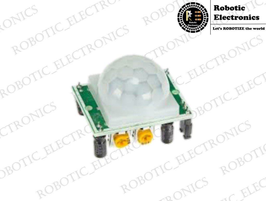
PIR Sensor motion PIR in PIR Sensor stands for a passive infrared sensor it is used to detect the motion of an object, person, or any other thing. PIR SENSOR is mainly used in the place where there is a need for detection of motion like in smart dustbin, the sensor just tells the controller that there is an object and that lets the dustbin door open. A PIR sensor looks like below which is interfaced with an opensource board like Arduino, raspberry pi and many more  It is a passive component that consists of a pyroelectric sensor that detects the heat changes around it and gives a high value as an output.  This is how a PIR sensor look like       Actually, under the white plastic dome-shaped material there is a pyroelectric sensor. This white cap is called frensal glass that converges all the rays towards the center where the pyroelectric sensor is present. Let us discuss each part briefly one by one with their use and need below Pyroelectric sensor The pyroelectric sensor is a sensor which gives us a high value when it detects any infrared radiation in its area. As we know that everybody emits infrared rays even we human beings also emit some infrared waves though they are not that strong. These rays are enough for a pyroelectric sensor to give an output. A pyroelectric sensor looks like below Now then it is mounted by a fresnel glass. Frensal glass The main aim of this frensal glass is to converge all the infrared radiations to the pyroelectric sensor present in the middle. The dome is designed in such a way that all the rays converge at a point that gives the user accurate output. Now let’s discuss the other important parts of it Vcc The Vcc pin provides power supply to the sensor it ranges from 3 to 5 volts as the sensor works at an operating voltage of 3v there is a step-down transformer to convert 5v supply to 3v. Ground It consists of a general ground pin to complete the circuit which is connected to the ground pin in the Arduino board. Data pin in PIR Sensor Data pin gives the output which acts as input to the Arduino board it gives only two values high or low high indicates there is a change or motion detected and low indicates there is no motion change. There are two potentiometers present near the end Potentiometer.1 Delay time adjust Delay time adjust potentiometer allow us to change the cycle time so that we can detect the motion for regular intervals. Potentiometer.2 Sensitivity adjust It is used to adjust the range. We can set our range for longer to shorter distances using this potentiometer. Retriggering jumper This helps us to switch between two modes one mode provides continuous information about the motion while the other provides us the information for regular intervals. Specifications Wide Working Voltage Range: DC 4.5V- 20V  Current Drain: <60uA  Detection Angle: <140°  Detection Distance: 3 to 7m (can be adjusted)  Blockade time: 2.5s (Default)  Work temperature: -20-+80°C  Hope this article helps you in understanding the motion sensor.  For any queries, the comment section below is always open for you.

Gas sensor

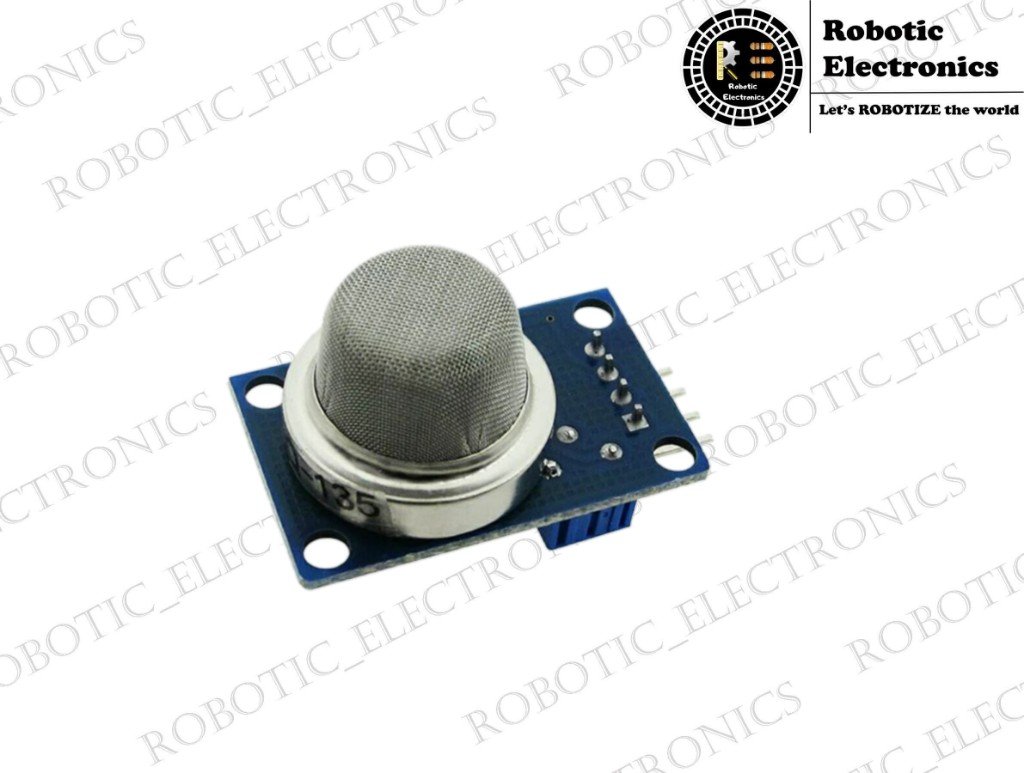
GAS SENSOR Hello geeks in this article I am going to share information about the various gas sensor and also their working principle. There are very interesting phenomena in the working of gas sensor I will share that information with some illustrations in this article. First of all, we get a doubt about what is a gas sensor, why we need it? What is the working principle behind it?  What are the different gas sensor and where do we use them?  Don’t worry, I am going to answer all these questions in this article.  Our first question is very simple to answer a gas sensor is a device that senses the gas around it and gives us the output either in a digital signal for continuous-discrete values as an analog signal. When when we come to the next question of why we need it then the reason is to identify the gas leakage in the home, industries, hotels and they are also used for detecting the alcoholic people. It is used to detect flammable,  toxic gases in petroleum and some other industries. They are also needed in mining areas. External appearance A typical gas sensor consists of a semiconductor material enclosed in a mesh-like material to prevent the contact of unwanted dust particles with the sensitive semiconductor material as shown in the below figure. It consists of six pins they are namely two H pins in the middle and the remaining are pair of A pins on either side and likewise two B pins as shown in the below figure. 2,5 are H pins 1,3 are A pins 6,4 are B pins Now when we come to the pins connected to the module there are four pins and namely, they are 1. Vcc 2. Digital signal pin. 3. Analog signal pin. 4. Ground pin. Working principle : A simple gas sensor is made up of very sensitive semiconductor material and it is SnO2. The conductivity of this material changes the concentration of the gas present around it. Higher the gas content present, the higher is the conductivity of that material. the circuit diagram is very simple to understand and it is like below Voltage is applied to the heater that initiates the semiconductor to work when the voltage across the A and B pins vary according to the gas content due it’s conductivity and it is treated as an output signal. For the better performance, two pairs of A and B pins are used and these pins are interchangeable as the material is simply resistor and it is a bilateral element. Voltage fluctuations at A and B pins act as a signal data line to the microprocessor and help us to draw the outputs.  That is the simple principle behind the working of the gas sensor. Now I will discuss the various gas sensors. There are many gas sensors in the MQ series with names MQxx starting from 2 to 10 and each has its significant use and purpose MQ-2 is for detecting General combustible gas MQ-3 is for detecting the Alcohol. MQ-4 is for detecting Natural gas, Methane MQ-5 is for detecting LPG, Natural gas, Coal gas MQ-6  is for detecting LPG, Propane MQ-7 is for detecting Carbon Monoxide MQ135 is for detecting Air Quality Control   Still, there are many more models present in the market. I think with this article you could understand the principle behind the working of a gas sensor and basics of it. For any queries, the comment box below is always open for you. I will be back with new interesting information once again. Also read:Color sensorsArduino weather station

Color sensor

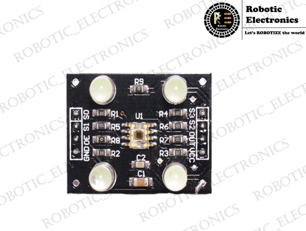
Color sensor Hello, geeks, We are back with a new interesting article on the color sensor (TCS3200)  and also its working principle. It has a very interesting phenomenon in the working of color sensor I will share that information with some illustrations in this article. First of all, we get a doubt about what is a colour sensor, why we need it? What is the working principle behind color sensor? Don’t worry, I am going to answer all these questions in this article.  Our first question is very simple to answer a color sensor is a device that senses the color of the object present in its vicinity by giving different RGB values.  Every color in this world is made of a combination of red, green and blue colors. The change in the percentage of these three colors leads to different colors. Every color is identified by the percentage of red, green and blue colors present in it. External appearance of color sensor : Now let’s discuss the external look of the color sensor TCS-3200. The module looks as in the below figure with 4 LED lights on the four corners of the device for the greater luminescence. It contains 8 pins to be connected to a microcontroller that I will discuss below. A color sensor consists of an 8×8 array of Photodiodes. Out of which 16 are Red filter photodiodes, 16 are Green filtered photodiodes, 16 are Blue filtered photodiodes and remaining are no filter photodiodes. All these same color photodiodes are connected in parallel for accurate output to the microcontroller. The sensor array looks like below. Working: Now when we come to the working of the TCS3200 it is a programmable color light to frequency converter that contains photodiodes and current to a frequency converter. The output is a square wave with the frequency directly proportional to light intensity. The block diagram looks like TCS3200 contains 8 pins namely they are Vdd, Gnd, OE, S0, S1, S2, S3. The input out pins are given as below and their functions in the third column. TERMINAL NAME     NO. I/O DESCRIPTION GND 4   Power supply ground. All voltages are referenced to GND. OE 3 I Enable for f0 (active low). OUT 6 o Output frequency (f0). SO, S1 1,2 I Output frequency scaling selection inputs. S2, S3 7,8 I Photodiode type selection inputs. Vdd 5   Supply voltage Selectable options:   S0 S1 OUTPUT FREQUENCY SCALING (Qf) L L Power down L H 2% H L 20% H H 100% S2 S3 PHOTODIODE TYPE L L Red L H Blue H L Clear (no filter) H H Green Usually, we use S0-H, S1-L with 20% output frequency scaling. Here below I am leaving the code for the color detection the color can be noted by its RGB values on the Serial monitor. Here are the connections between the TCSP3200 and the Arduino: S0: digital pin 4 S1: digital pin 5 VCC: 5V S3: digital pin 6 S4: digital pin 7 OUT: digital pin 8 Code 1. Reading the output frequency Upload the following code to your Arduino board. Applications of TCS3200  1. In low-level projects for primary identification of objects by color instead of going for image processing.  2. In color sorting machines.  3. In toys for children to learn colors.  Stay tuned on this site. We will be back with interesting articles on various sensors Also read about:8051 microcontroller

MOTOR DRIVER INTERFACING WITH ARDUINO

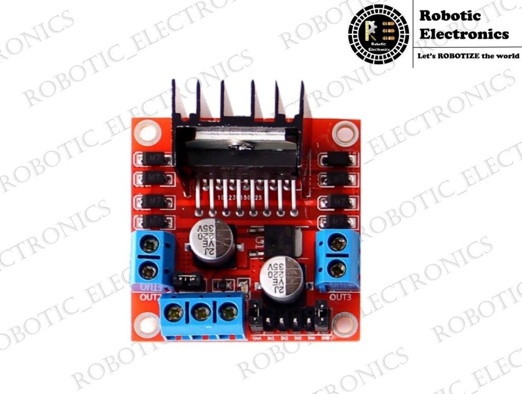
MOTOR DRIVER INTERFACING WITH ARDUINO A motor driver is an electronic component that uses the principle of H-bridge to control the output voltage and the direction of rotation of the motor. An L298N (motor driver) consists of four output pins, four input pins, three power pins and two pairs of enabling pins as shown in the below figure. L298N pinout The board has a premounted 5V regulator to maintain a constant output voltage of 5V at every output pin. A motor driver is a type of input amplifier. It amplifies the signal that comes from the Arduino and provides at the output because the only microcontroller cannot deliver a full output voltage to run the motor at rated speed.  The power pins are used to powerup the motor driver with an external power source and input pins get information from a microcontroller, in our case that is Arduino, to control the direction of motors. The same configuration applies for L293D also, but the difference comes in them with the pair of enabling pins and power withstanding capacity of L298N. INTERFACING L298N with ARDUINO:- The Arduino interfacing with the L298N is given below. The 12V pin is connected to the positive of the battery. 5V pin of the motor driver is connected to 5V of Arduino. The ground pin of the motor driver is connected to the battery negative and one of the ground pin of Arduino. The four input pins are connected to the digital pins of Arduino as shown in the figure. The four output pins of the motor driver are connected to the terminals of the motor. See that connections are made properly and be careful with the terminals of the battery. See that the ground pin and 12V pin do not touch each other as it will lead to the failure of the battery and L298N module. WORKING EXPLANATION OF L298N Generally, a motor works when there is a potential difference between two of its terminals. This potential difference is created and controlled by the Arduino (microcontroller unit). We know that we can program output voltages in Arduino. Using two digital pins with one as HIGH and one as LOW we are creating a potential difference between the terminals of the motor. One pin of the motor will be in higher potential and others will be in lower potential. If the voltage at terminals is interchanged means HIGH in above is made LOW and LOW is made HIGH then the direction of the motors is reversed. If both the terminals are given as either LOW or HIGH then we can see that there is no potential difference between the terminals therefore the motors won’t run. In this way, we can control the direction of rotation of motors. Arduino program of L298N CONCLUSION Hence here about interfacing of Arduino with motor driver and its working, operations are discussed Also read about Arduino

IR SENSOR INTERFACING WITH ARDUINO UNO

IR SENSOR INTERFACING WITH ARDUINO UNO IR sensor is an electronic component that is used to sense certain characteristics of its surroundings. It does this by either emitting or detecting infrared radiation. Infrared sensors are also capable of measuring the heat being emitted by an object and motion detection. IR sensor interfacing with arduino UNO Wavelength regions of Infrared Spectrum Near IR – 0.75micrometers to 3micrometers. Mid IR – 3micrometers to 6micrometers. Far IR – > 6micrometers. How Infrared Sensor Works An Infrared Sensor works in the following sequence: IR source (transmitter) is used to emit radiation of the required wavelength. This radiation reaches the object and is reflected. The reflected radiation is detected by the IR receiver. The IR radiation detected by the receiver is then further processed based on its intensity. Generally, the IR receiver output is small and amplifiers are used to amplify the detected signal. IR sensor FC-51 The sensor used in our demo is model is FC-51. It is easily available on the internet for less than $2. Pin, Control Indicator Description Vcc 3.3 to 5 Vdc Supply Input GND Ground Input Out The output that goes low when an obstacle is in range Power LED Illuminates when power is applied Obstacle LED Illuminates when an obstacle is detected Distance Adjust Adjust the detection distance. CCW decreases distance.CW increases distance. IR Emitter Infrared emitter LED IR Receiver An infrared receiver that receives a signal transmitted by Infrared emitter. Connecting the IR sensor with Arduino Connecting Arduino with IR Sensor is explained in the following steps: Connect the -ve wire on the IR Sensor to GND on the Arduino. Connect the middle of the IR Sensor which is the VCC to 5V on the Arduino. Connect the signal pin on the IR sensor to pin 8 on the Arduino. Source code for Interfacing IR sensor with Arduino. Conclusion: The above-discussed information about the IR Sensor is all about the interfacing and functioning of the Sensor with the ARDUINO Development Board. In this way, the IR sensor component can be connected to the ARDUINO and can be used for a wide range of applications in the Autonomous Robotic Projects. Read related topics: Introduction to arduino boardInterfacing of arduino with joystick modulearduino official website tutorials